Treating a volume booster as a cure for every slow valve can send a project toward the wrong modification. ControlAir announced the Type 625 as a pneumatic relay for increasing available airflow between a valve positioner and pneumatic actuator; a closer evaluation starts with the existing air-delivery path and required response.
The ControlAir Type 625 volume booster follows a pneumatic pressure command while making supply air available to the actuator. It is a candidate for an airflow-limited application, subject to compatibility review, rather than a replacement for the positioner. This page turns the announcement into a system checklist: identify the command and supply paths, collect actuator and positioner information, and plan how to evaluate response. Faster motion and stable control are manufacturer claims, not results measured by this site.
- The positioner, booster and actuator have different jobs.
- Small adjustments and larger movements deserve separate review.
- A product announcement is enough to begin a document review, not to approve a retrofit.
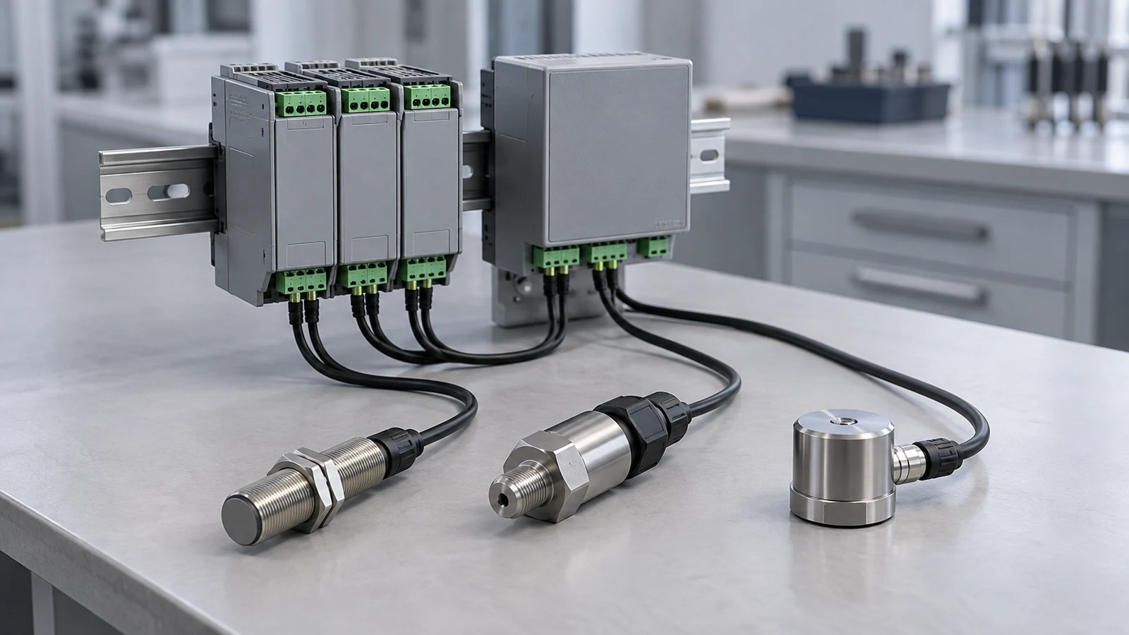
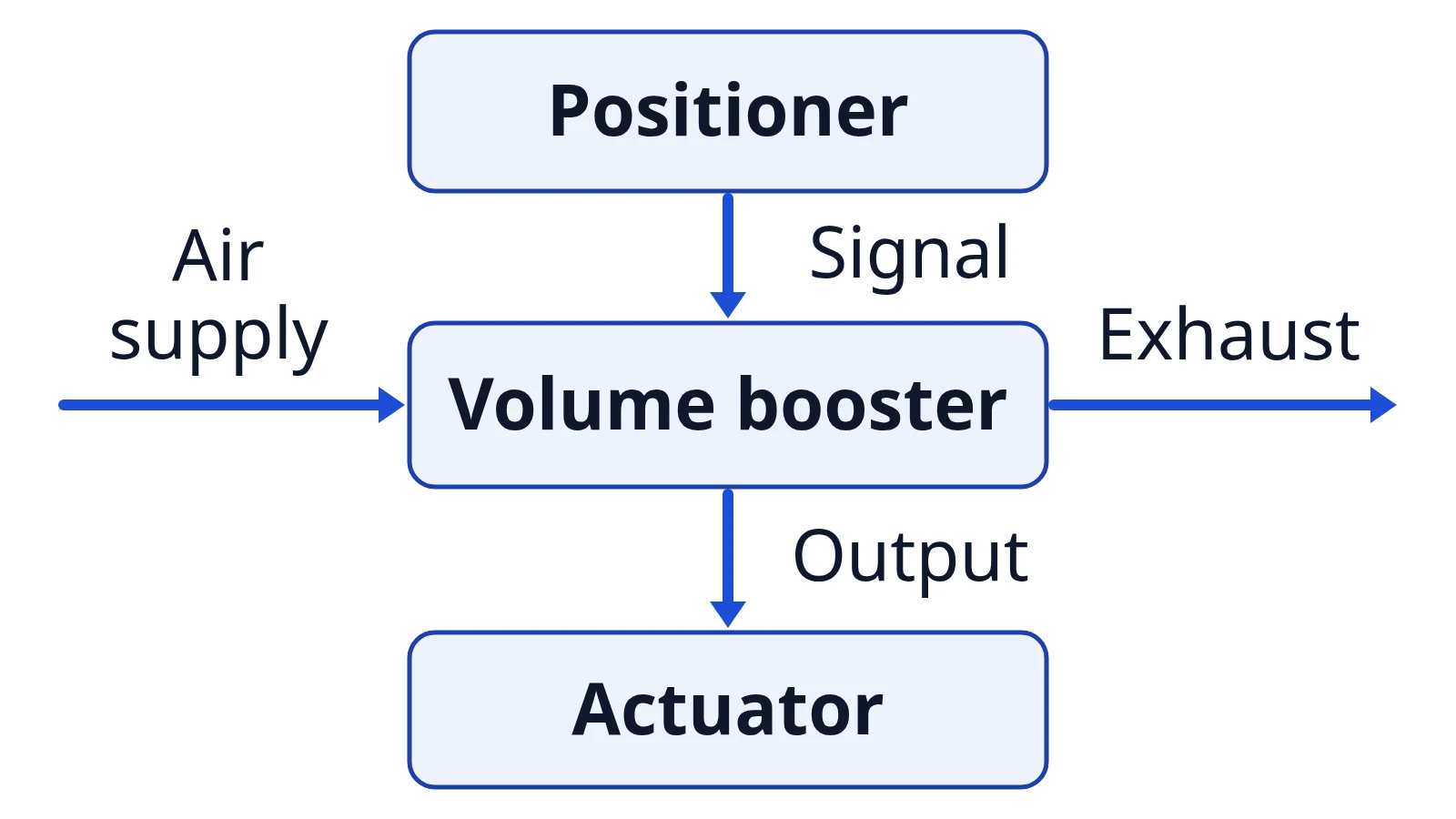
The opening image and diagrams below are editorial schematics, not product photographs or installation drawings. This is an independent publication; our About page explains the site’s identity.
What was announced, and when?
ControlAir introduced the Type 625 as a compact pneumatic relay intended to improve actuator response by increasing available airflow. The earliest report reviewed for this article is dated September 30, 2026. Those are announcement claims; neither report supplies an independent before-and-after trial on a specified valve assembly.
| Event | Date | Source and status |
|---|---|---|
| Type 625 announcement covered | September 30, 2026 | Compressed Air Best Practices; reports ControlAir’s product claims |
| Further announcement coverage | October 5, 2026 | Fluid Power World; repeats core positioning and feature language |
| Product documents and reports reviewed for this page | October 8, 2026 | Editorial review; no installation or field test |
The two reports establish how the product was presented. Their overlapping descriptions do not amount to two independent demonstrations of faster response. The first report’s date also does not establish a shipping date or the precise date of the manufacturer’s original announcement.
Takeaway: Use the reports to identify the new product, then use the manufacturer’s documents to investigate fit.
Where does it fit between positioner and actuator?
The booster belongs in the pneumatic delivery path: the positioner supplies the pressure command, the booster uses that command to control downstream air, and the actuator produces motion. ControlAir’s operating-principle explanation distinguishes signal pressure, supply pressure, downstream pressure and exhaust. Draw those paths separately before reviewing a proposed connection.
| Part or path | Role in this review | Information to identify |
|---|---|---|
| Positioner | Compares requested and actual valve position and adjusts pneumatic output | Model, output arrangement and feedback connection |
| Booster signal | Pilot-pressure command | Which positioner output supplies it |
| Booster supply | Air available for downstream delivery | Supply arrangement and applicable limits |
| Booster output and exhaust | Delivery to, and release from, the downstream pneumatic circuit | Actual piping and actuator arrangement |
| Actuator | Converts pneumatic action into movement | Type, volume and required movement |
ControlAir specifies a 1:1 signal-to-output pressure ratio in its Type 625 product description and specification sheet, reviewed October 8, 2026. This describes pressure following. It is neither an air-volume multiplier nor a formula for predicting stroke time.
The electrical or network command upstream is a separate interface question. Our industrial sensor signal-and-interface table helps distinguish a recorded measurement or electrical interface from the pneumatic pressure path shown here.
Common mistake: Treating “booster” as a promise of higher commanded pressure. The Type 625’s published role is increased airflow with pressure following, not an arbitrary increase in the requested actuator pressure.
Takeaway: Label command, supply, output and exhaust on the system sketch rather than drawing a single unspecified “air” line.
Why do the bypass and deadband matter?
ControlAir describes a fixed deadband and an adjustable bypass that let small downstream pressure adjustments occur without opening the main booster valve. The same documentation presents the bypass as a way to tune dynamic response. That explains why reviewing only a large movement would leave part of the intended behavior unevaluated.
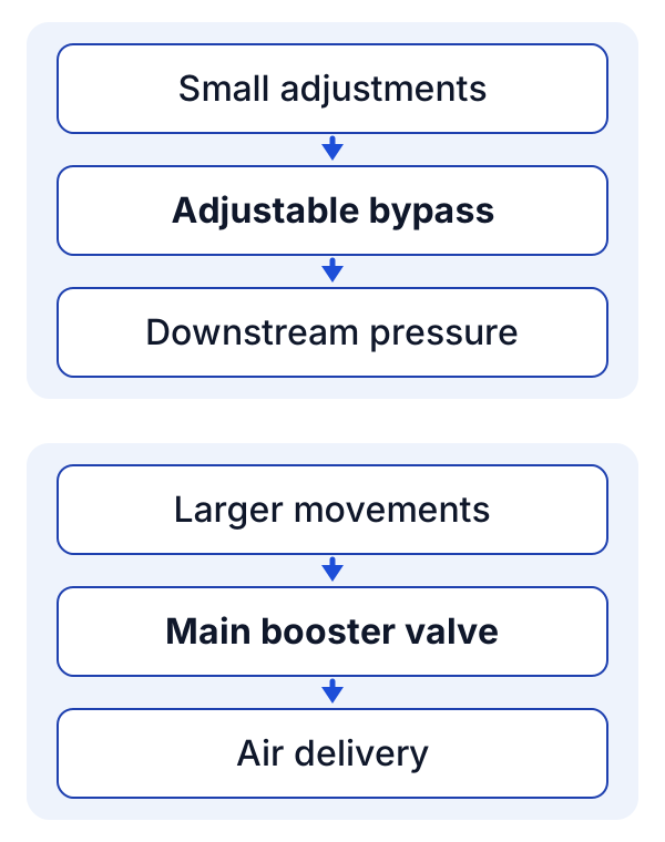
Editorial schematic based on ControlAir’s Type 625 description. It shows functional paths, not internal construction or a bypass setting.
For a project review, distinguish the ability to make small corrections from the ability to complete larger commanded movements. Decide what records would show each behavior in the intended assembly. Our pressure-transducer and displacement-sensor comparison explains why pressure and position are different measurements; a pressure record alone should not be presented as a measured valve-position result.
There is no bypass opening, adjustment sequence or acceptable overshoot value specified in this article. Obtain the applicable installation and tuning instructions for the selected assembly before making adjustments.
Takeaway: Ask how both small corrections and larger movements will be evaluated, without inventing a bypass setting.
Who should consider a closer look?
Engineers with a pneumatic actuator whose required movement warrants an air-delivery review are the main audience. ControlAir identifies diaphragm and piston actuators, including large-volume applications. The relevance is a reason to investigate the circuit; it does not establish compatibility with every actuator in those categories.
| Reader or situation | Useful next decision | Basis |
|---|---|---|
| Valve engineer reviewing slow movement | Determine whether the pneumatic delivery path deserves investigation | Manufacturer’s airflow-focused product positioning |
| Integrator specifying a larger-volume actuator | Compare the existing positioner output arrangement with the actuator’s requirements | Manufacturer’s stated application scope |
| Team concerned about settling or repeated corrections | Include small-command behavior in the evaluation plan | Manufacturer’s bypass and dynamic-response description |
| Maintenance team without a system baseline | Collect records before choosing a modification | Editorial recommendation; this page supplies no diagnosis |
For measurement planning, use the sensor-family table to identify the quantity being recorded. For other control-system topics, the Automation reading collection provides the next point of reference.
Takeaway: Establish the system question first; a larger actuator or slow response alone is not a completed product selection.
What should you check with the positioner?
Start with a documented assembly, not an accessory name. ControlAir’s selection guidance identifies actuator volume, required stroking speed, supply pressure and dynamic response as considerations. The following checklist expands those considerations into records for an engineering review; it is an editorial aid, not a manufacturer’s approval procedure.
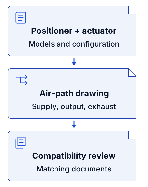
An editorial document sequence. Completing a box means the information is recorded, not that the assembly has passed a test.
| Record | What to collect | What the review should resolve |
|---|---|---|
| Positioner | Exact model, documented pneumatic output range and current configuration | How its output would command the booster |
| Actuator | Model, type, volume and operating documentation | Whether the proposed circuit matches the actuator arrangement |
| Required response | Intended movement and how success will be judged | What the evaluation actually needs to demonstrate |
| Air path | Available supply pressure, documented signal/output limits, tubing, fittings and exhaust path | Whether pressures and the delivery arrangement match the selected components |
| Configuration | Selected booster version, operating temperature and applicable site/environment requirements | Whether recorded conditions match its operating limits and instructions |
| Baseline | Available command, position and pressure records | What can be compared before and after a proposed change |
If the records come from different instruments or systems, identify their interfaces and time basis before interpreting them together. The industrial measurement selection checklist covers the measurement inputs and conditions to record. Keep that measurement plan separate from approval of the pneumatic assembly.
Common mistake: Writing “faster” as the acceptance criterion without saying which movement, operating condition or observation defines success. A catalog claim does not supply the project’s acceptance test.
Takeaway: Finish the input record before asking whether the proposed booster and positioner combination meets the task.
When should a project act?
Begin a document review now if the announcement matches an existing engineering question. Make installation or tuning decisions only after the assembly and applicable instructions have been reviewed. Procurement has its own timing: neither the September 30 nor October 5 report confirms availability for a particular region or delivery window.
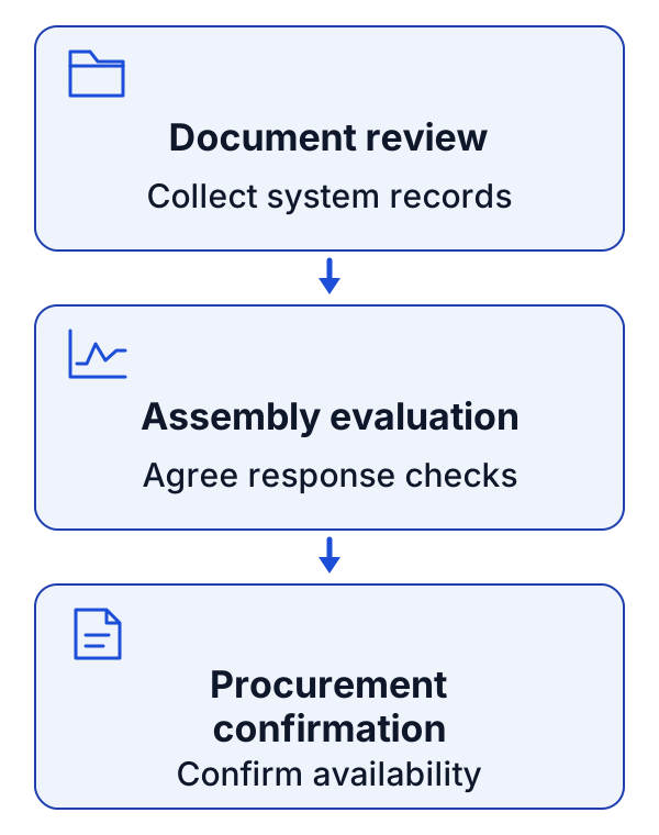
Suggested review stages, not a commissioning procedure or a supplier schedule.
- At the October 8, 2026 review point: collect the product documents and fill in the compatibility record.
- Before an engineering change: agree on the assembly, instructions and response evaluation with the responsible engineer.
- Before a procurement commitment: confirm the selected configuration, regional availability and delivery terms with the supplier.
For a review that also changes networked measurement equipment, consult the connected-sensor security baseline. That applies to the connected measurement system, not to an assertion that the pneumatic booster itself is an IoT device.
Takeaway: Separate the date of a news report from the project’s technical and procurement decision points.
When this does not apply
This checklist addresses pneumatic actuator air delivery. It does not establish a remedy for an electric actuator, an unidentified mechanical problem, or a fault elsewhere in the process loop. It also does not supply a construction drawing, a live-system adjustment procedure, or an approval for a safety-related or hazardous-location installation.
The article cannot identify the cause of a particular slow valve from the announcement. Where the cause is unknown, record the symptom and have the responsible engineer decide what evidence is needed before specifying a change. The Sensors and DAQ collection offers background for choosing measurements, rather than a diagnosis of the valve.
Takeaway: Use the checklist to organize an evaluation within its scope, not to justify an unreviewed modification.
What is still uncertain?
The unresolved questions concern the reader’s assembly and procurement, not whether the announcement exists. Turn each unknown into a document or observation that someone can provide. This keeps the review actionable without converting the manufacturer’s intended benefits into guaranteed field results.
| Unresolved item | Who can confirm it | Evidence to obtain |
|---|---|---|
| Actual response improvement and settling behavior | Responsible engineering team | Results from the intended assembly under recorded conditions |
| Positioner and actuator compatibility | Assembly engineer and relevant manufacturers | Matching model documentation and reviewed circuit |
| Bypass adjustment and commissioning details | Responsible engineer using manufacturer instructions | Applicable instruction revision and agreed evaluation method |
| Configuration suitability for the location | Project engineer and manufacturer | Exact configuration documentation and site requirements |
| Regional availability and delivery | Supplier | Current written confirmation for the selected configuration |
There is no price, lead-time estimate or measured improvement percentage in the sources used here that this article adopts as a project result.
Takeaway: Assign each unknown to an evidence owner before it becomes a selection assumption.
Method and sources
This page is compiled from public manufacturer material and the two dated trade-press reports listed below. The reports were read in archived library versions fetched October 7, 2026; the manufacturer’s product page, specification sheet, operating-principle explanation and positioner documentation were checked October 8, 2026. The overlapping reports are treated as one announcement source family, not independent performance verification.
The function descriptions and pressure ratio come from ControlAir. The compatibility record and staged review are editorial recommendations. This site conducted no product test, and the diagrams do not reproduce the Type 625’s physical construction. Installation instructions could not be retrieved during this review, so no installation or tuning procedure is given. Version: initial article, October 8, 2026.
Related reading
- Industrial IoT sensors — Map a measurement from sensing element to control-system record.
- Strain gauge vs load cell and other sensors — Distinguish pressure, displacement and force measurements when planning evidence.
Use the compatibility table above as a project note, then follow the relevant measurement guide to define the records your review needs.