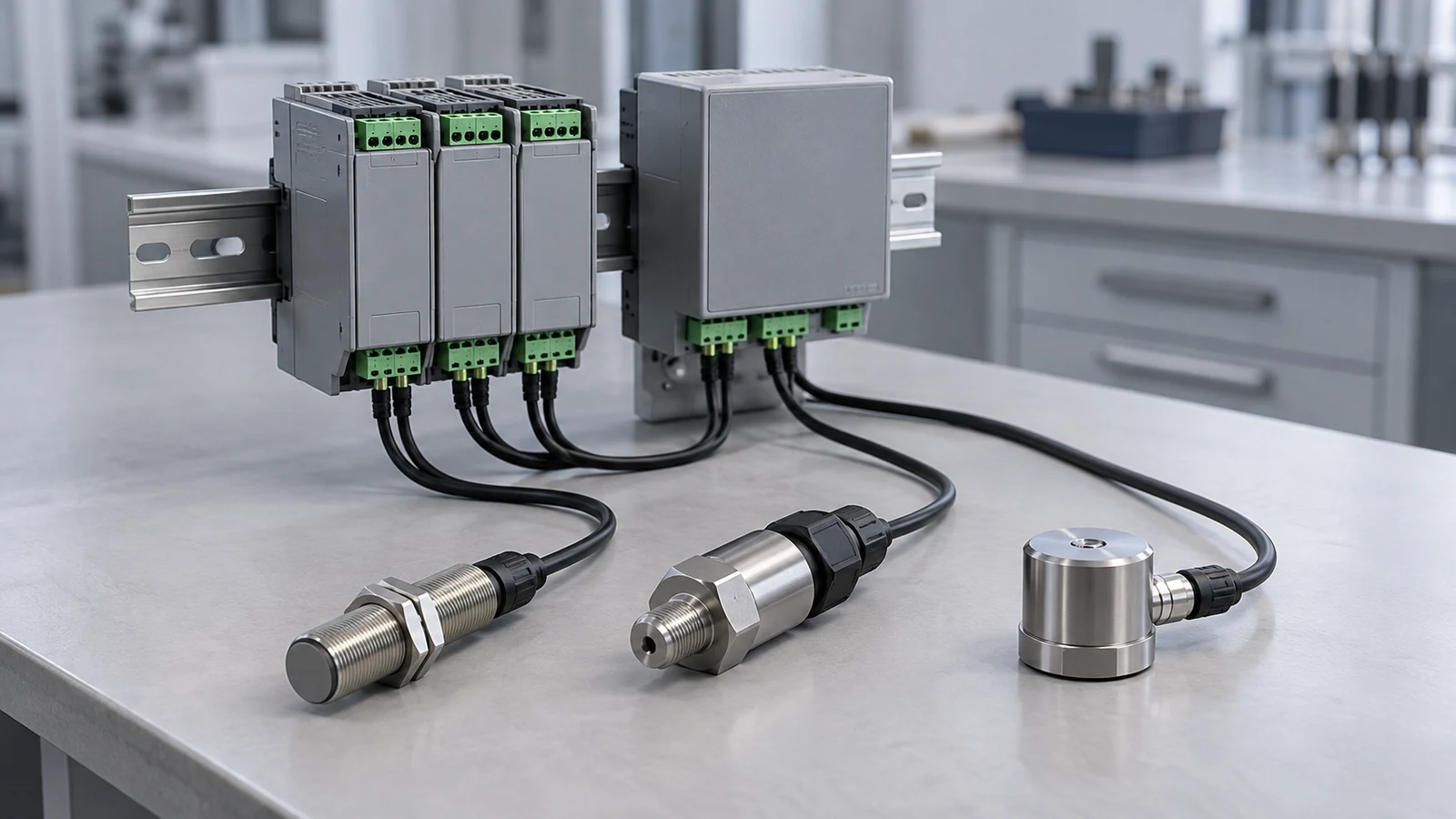
Choosing an industrial IoT sensor by its wireless badge instead of its measurand and output causes rework when it reaches the control system. An industrial IoT sensor is a sensing element plus electronics that measures a physical quantity and delivers it to a controller, gateway or data platform, as a 4–20 mA signal, over a protocol such as HART, IO-Link, Modbus or OPC UA, or through a wireless network.
Start from what you must measure and what your control system can receive, then pick the connection. 4–20 mA loops carry one value across a configured range, and FieldComm Group says more than 40 million installed field instruments support HART digital data on those loops; IO-Link (IEC 61131-9) connects individual sensors point to point over a standard three-wire cable; Ethernet protocols and OPC UA move data between devices and systems; WirelessHART and LoRaWAN cover places where cables are impractical. Security belongs in the specification: NIST IR 8259A gives six baseline capability areas to turn into purchase questions, chosen by risk.
This is a first selection for engineers and buyers planning data acquisition for the first time; it does not replace datasheets or site design. The result is a one-page sensor requirement (template below the five steps).
Quick specs for a first selection:
| Input or item | Typical value or source | Why it matters |
|---|---|---|
| Measurand and range | Your process data: temperature, pressure, force, vibration, position, level, flow, composition | Picks the sensor family |
| Accuracy and conditions | Datasheet linearity or accuracy with its test conditions | Resolution alone does not tell you accuracy |
| Analog output | 4–20 mA across the configured range; where NAMUR NE43 is implemented, 3.8–20.5 mA is measurement and ≤3.6 mA or ≥21.0 mA is failure information (Beckhoff manual) | Check that transmitter and input card use the same range, scaling and alarm settings |
| Digital over analog | HART on the 4–20 mA loop (FieldComm Group) | Adds diagnostics without new wiring |
| Point-to-point digital | IO-Link, IEC 61131-9; 3-wire; 4.8, 38.4 or 230.4 kBaud (IO-Link Community) | Parameters and diagnostics per sensor via an IO-Link master |
| Wireless | WirelessHART mesh with gateway; LoRaWAN low-power wide-area (FieldComm Group, LoRa Alliance) | Confirm gateway or network, power source and update rate per device |
| Environment | Temperature, ingress protection, hazardous-location approval | Decides whether a sensor may be installed at all |
| Security baseline | NIST IR 8259A: six capability areas, selected by risk | Sets what to ask suppliers before connecting |
This guide is compiled from standards bodies’ and industry organizations’ public material by an independent site (about this site); it does not rank products.
What makes a sensor an industrial IoT sensor?
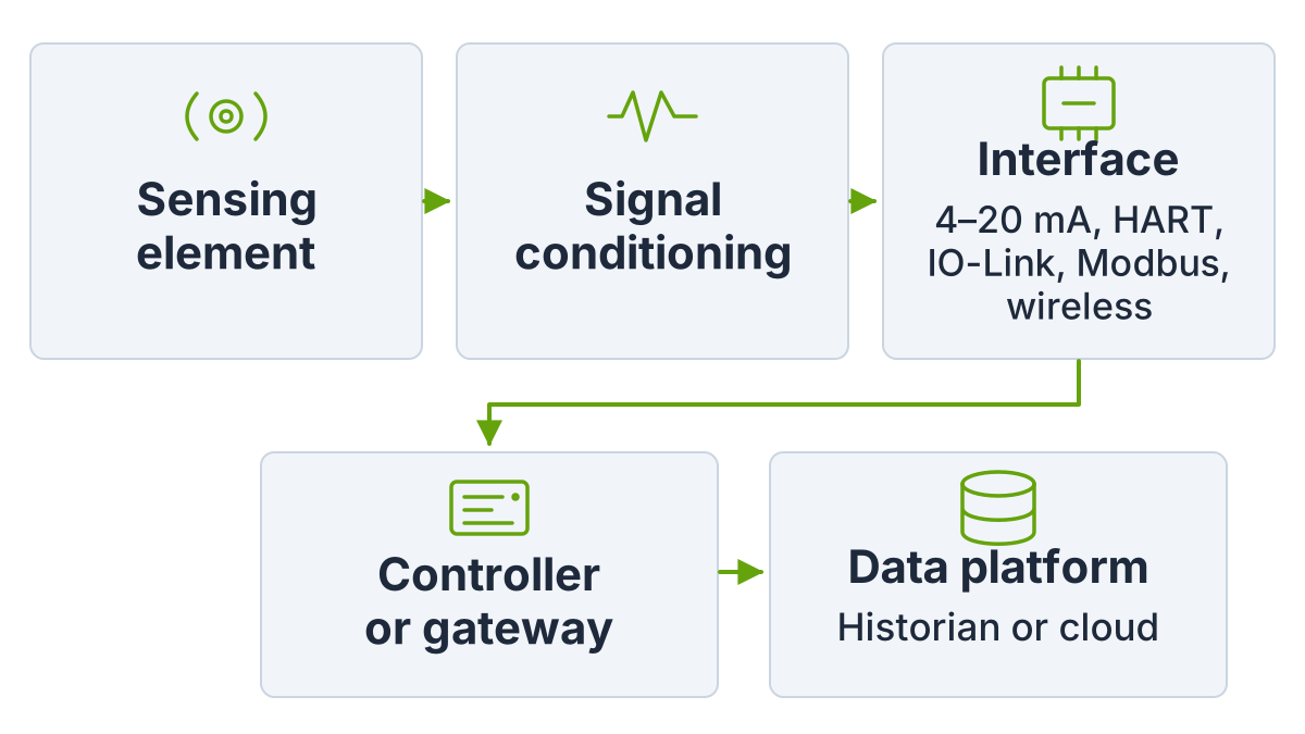
A sensor becomes part of an industrial IoT system when its measurement reaches a network in a form other systems can use, with enough context to trust it. The sensing element is often the same as in a conventional instrument; the difference lies in the electronics and the path the data takes.
| Stage | What happens | Example |
|---|---|---|
| Sensing element | Converts the physical quantity into an electrical change | Strain gauges on a diaphragm in a pressure sensor |
| Signal conditioning | Excitation, amplification, linearization, digitizing | Bridge amplifier for a load cell |
| Interface | Sends the value as a current, a protocol message or a radio packet | 4–20 mA, IO-Link, Modbus, WirelessHART |
| Controller or gateway | Uses the value for control or forwards it | PLC, DCS, edge gateway |
| Data platform | Stores and analyzes values over time | Historian, cloud service via OPC UA or similar |
Strain-gauge sensing is a good example of a sensing element that appears in many products; our strain gauge explainer shows how it works from the inside.
Takeaway: Describe the full path from element to data platform before choosing any one device.
Which sensor types measure what?
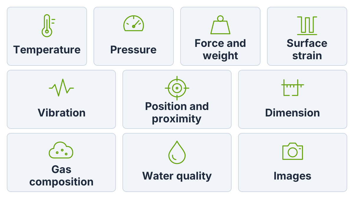
Sort sensors by the quantity you need, then by the operating principle that suits your conditions. The table lists the common industrial families and where to read more on this site.
| Measurand | Common sensor types | Typical industrial use | |
|---|---|---|---|
| Temperature | RTD (resistance), thermocouple (thermoelectric voltage), thermistor | Process lines, bearings, ovens | — |
| Pressure | Strain-gauge or piezoresistive diaphragm transducers | Hydraulics, pneumatics, process lines | Sensor comparison table |
| Force and weight | Strain-gauge load cells | Weighing, filling, test rigs | Strain gauge vs load cell |
| Surface strain | Bonded strain gauges | Structural and machine monitoring | Strain gauge basics |
| Vibration | Accelerometers | Motor and pump condition monitoring | — |
| Position and proximity | Inductive proximity sensors, LVDTs | Machine positions, end stops | LVDT in the comparison |
| Dimension | Optical micrometers, laser gauges | Inline quality control | profileGAUGE C.ODC specs |
| Level | Level sensors; principle depends on liquid or solid and vessel | Tanks, silos | — |
| Flow | Flow meters; principle depends on fluid and pipe | Process lines, utilities | — |
| Gas composition | Gas analyzers | Emissions and gas quality | QX1400 certification explainer |
| Water quality | Online analyzers | Wastewater, reuse | BactoSense ID explainer |
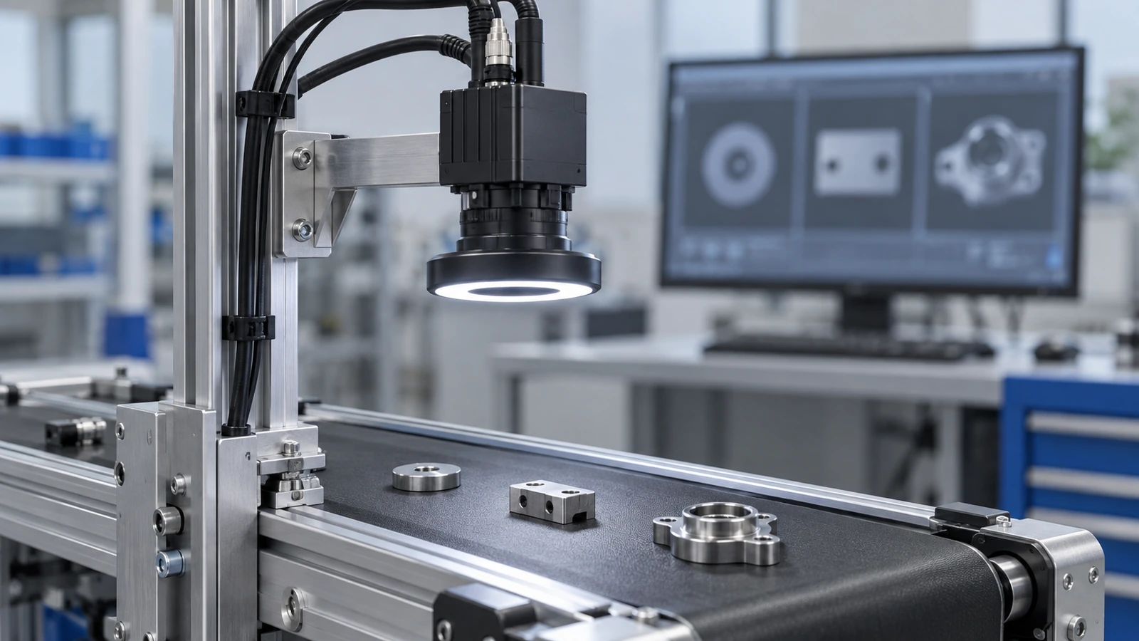
| Images | Machine-vision cameras | Inspection, identification | MVTec AI Vision Solver note |
For force, weight and pressure, the comparison of strain-gauge sensors, LVDTs and extensometers is the next step; for inline dimensional gauges, see how a datasheet states accuracy in the profileGAUGE C.ODC reading.
Takeaway: Fix the measurand and range first; the sensor family usually follows directly.
How do sensor signals reach the control system?
Pick the interface your control system already supports unless a new one adds something you need, such as remote parameter setting or diagnostics. Each option carries different wiring, configuration and data.
| Interface | What it carries | Wiring or network | Strength | Watch for |
|---|---|---|---|---|
| 4–20 mA | One analog value across a configured range | Current loop; loop-powered transmitters exist | Simple wiring; NE43 failure signalling where configured | One value per pair; range, scaling and alarms must match the input card |
| HART | Digital data on top of 4–20 mA | Same loop | Diagnostics and configuration without rewiring | Host system must read HART |
| IO-Link | Process data, parameters, diagnostics | Point-to-point 3-wire to an IO-Link master | Remote parameter setting; standard M12/M8/M5 connectors | Needs masters; not a fieldbus itself |
| Modbus | Register values | Serial line or TCP/IP specifications; Modbus Security adds TLS | Published open specifications | Register map from each device’s documentation |
| Industrial Ethernet protocols | Cyclic process data | EtherCAT, PROFINET, EtherNet/IP and others | Uses the controller’s native network | Protocol and device description files must match the controller |
| OPC UA | Structured data with information models | Platform-independent; several transports | Encryption, authentication and auditing in the architecture | Decide where it runs: device, gateway or server |
| WirelessHART | HART data over a mesh network | Radio mesh plus gateway and network manager | Mesh routing gives redundant paths | Gateway and network manager required |
| LoRaWAN | Data from battery-operated devices | Low-power wide-area, unlicensed bands; the LoRa Alliance cites up to 15 km in rural areas | Long range, low power | Check update rate and network coverage per device |
| Cellular IoT | Device data over public networks | LTE-M, NB-IoT, 4G, 5G (as listed by an IoT operator) | Uses operator coverage | Check power, data plan and latency per device |
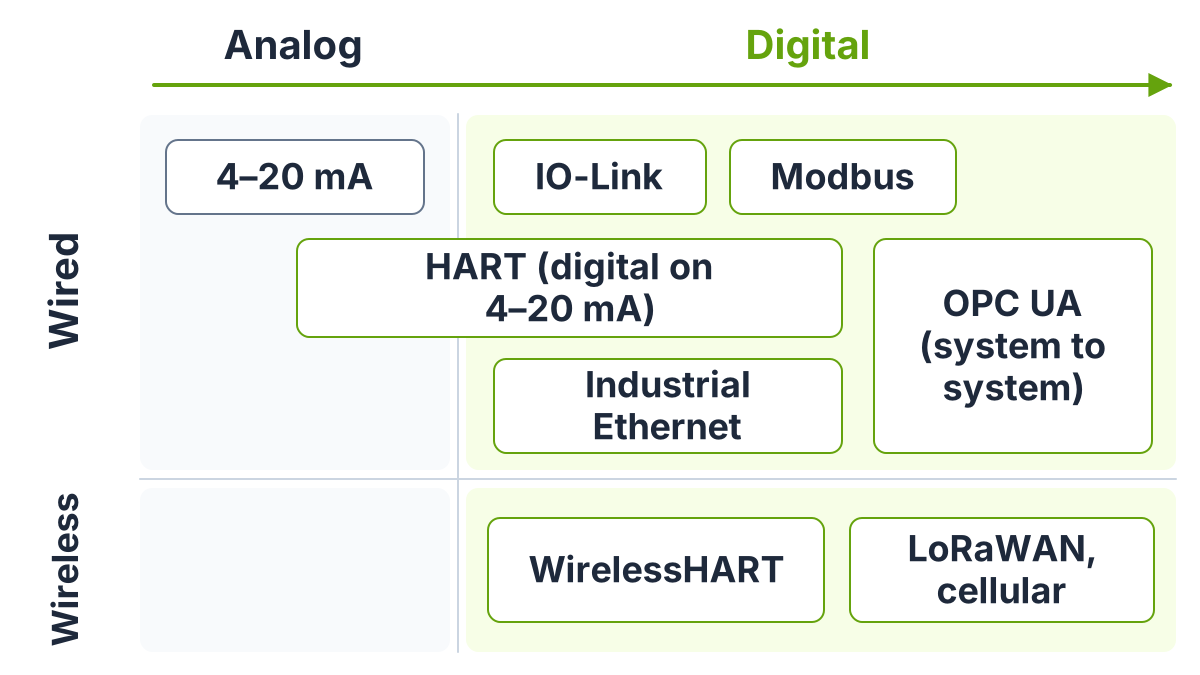
Real products mix these: Micro-Epsilon’s datasheet for one inline gauge (read 7 October 2026) lists Ethernet and RS422 as standard, with EtherCAT, EtherNet/IP and PROFINET via an interface module or on request, which is why the profileGAUGE C.ODC spec reading treats the interface as an item to confirm per model code.
Common mistake: Ordering a sensor whose protocol your controller does not speak and planning to “add a gateway later”. Each gateway is another device to configure, power, secure and maintain.
Takeaway: List the inputs and protocols your controller or DCS already supports before shortlisting sensors.
The 5-step industrial IoT sensor selection
Define the measurand and range, state accuracy with its conditions, check environment and approvals, match output and network, then settle power, data and security. Do them in order; each step removes options for the next.
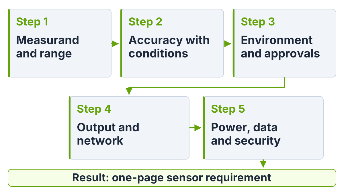
Step 1 — Define the measurand and range
Write the quantity, units, normal range, overload and update rate. A level sensor and a pressure sensor can both “measure a tank”, but they report different things.
Step 2 — State accuracy with its conditions
Ask for linearity or accuracy, repeatability and temperature effects under stated conditions. Resolution is only the smallest output step; the profileGAUGE C.ODC spec reading shows how far the two can differ on a real datasheet.
Step 3 — Check environment and approvals
Record temperature, moisture, washdown, vibration and whether the location is hazardous. In the US, OSHA 29 CFR 1910.307 lets classified locations use equipment that is intrinsically safe, approved for the location, or demonstrated safe, with specific provisions for Division 2; check the equipment and installation method against your area classification. Our QX1400 explainer walks through this for an analyzer.
Step 4 — Match output and network
Choose from the interface table, starting with what the controller already accepts. For wireless options, confirm the gateway or network, power source and update rate for each device.
Step 5 — Settle power, data and security
Decide loop power, 24 V supply or battery; data ownership and storage; and the security capabilities you require (next section).
Record the answers in a one-page requirement:
| Field | Your entry |
|---|---|
| Measurand, units, normal range, overload, update rate | |
| Accuracy figure and its conditions | |
| Environment: temperature, ingress, vibration, area classification | |
| Output or protocol, and the receiving controller or input card | |
| Power source; data destination; security capability questions | |
| Open items to confirm with the supplier |
Takeaway: Send the completed requirement to suppliers and your integrator together, so both answer the same questions.
What do industrial IoT sensors look like in practice?
A first deployment usually serves one clear job. The table pairs jobs with candidate sensors and interfaces; the pairings are illustrative, to confirm with suppliers.
| Job | Candidate sensors | Candidate interface | Related article |
|---|---|---|---|
| Machine condition monitoring | Vibration, temperature, motor current | IO-Link or a wireless option | — |
| Weighing and filling | Load cells | Bridge amplifier or weighing terminal to a fieldbus | Strain gauge vs load cell |
| Process measurement | Pressure, flow, level, temperature transmitters | 4–20 mA with HART | — |
| Emissions and gas quality | Gas analyzers | Analog outputs, Modbus or plant network | QX1400 explainer |
| Water and wastewater | Online quality analyzers | SCADA connection | BactoSense ID explainer |
| Inline quality control | Optical gauges, cameras | Industrial Ethernet | MVTec AI Vision Solver note |
Takeaway: Start a pilot with one job and one interface, then extend once data quality is proven.
What security baseline should a connected sensor meet?
Turn NIST’s six baseline capability areas into purchase questions, choose the ones your risk requires, and design the network to the ISA/IEC 62443 series. NIST IR 8259A presents the six as a starting point that organizations can extend, reduce or partly apply, not a complete definition for every case. For networked sensors, record separately what the sensor provides and what the gateway provides.
| NIST IR 8259A capability | Question to ask the supplier |
|---|---|
| Device identification | Does each device have a unique logical and physical identifier? |
| Device configuration | Can authorized users change and protect the configuration? |
| Data protection | Is data protected in storage and transit with proven methods? |
| Logical access to interfaces | Can network and local interfaces be restricted to authorized users? |
| Software update | Can firmware be updated securely, and how are updates delivered? |
| Cybersecurity state awareness | Can the device report its own security state? |
Simple 4–20 mA sensors have no network interface of their own, so these questions fall on the IO module, gateway or controller that digitizes them.
Common mistake: Connecting a sensor gateway straight to the internet for a quick dashboard. Plan it as part of the control system’s security zones from the start.
Takeaway: Put the six capability questions into the purchase specification for every networked device.
When does this not apply?
This method is a first selection for routine plant monitoring and control; these areas need their own rules and specialists:
- Safety-instrumented functions; sensors in safety systems follow functional-safety rules not covered here.
- Legal-for-trade weighing or custody transfer, where metrology approvals govern the choice.
- Laboratory test benches with dedicated data acquisition, where IoT connectivity adds little.
- Consumer and building IoT, which use different devices and networks.
Takeaway: Check that your application is plant monitoring or control before using this method as written.
Related reading
Pick the next read by the sensor family you landed on:
- Strain gauge basics — Understand the sensing element inside many pressure and force sensors.
- Strain gauge vs load cell — Compare strain, force, displacement, elongation and pressure sensors.
- profileGAUGE C.ODC specs — Read accuracy figures with their conditions.
More articles are collected under automation, sensors and DAQ and test and measurement.
Takeaway: Read the strain gauge pages next if your measurand is force, weight or pressure.
Method and update log
Compiled on 7 October 2026 from public pages of the IO-Link Community, FieldComm Group, OPC Foundation, LoRa Alliance, Modbus Organization, NIST and ISA, plus an encyclopedia article on current loops marked as such. Organization claims, such as installed-base or range figures, are attributed to those organizations. Last reviewed 7 October 2026.