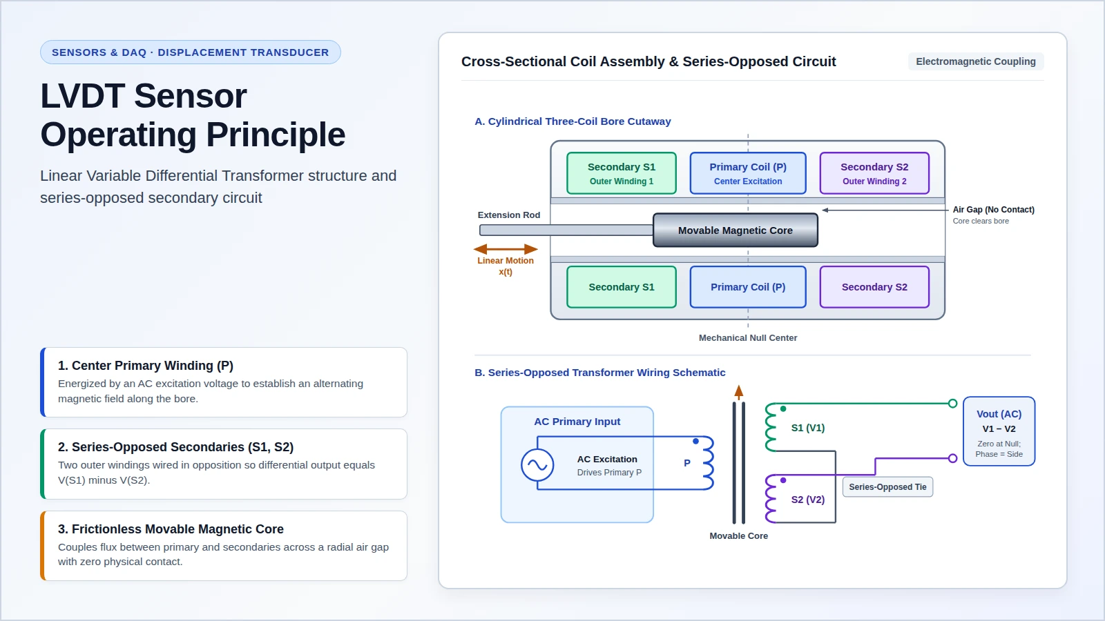
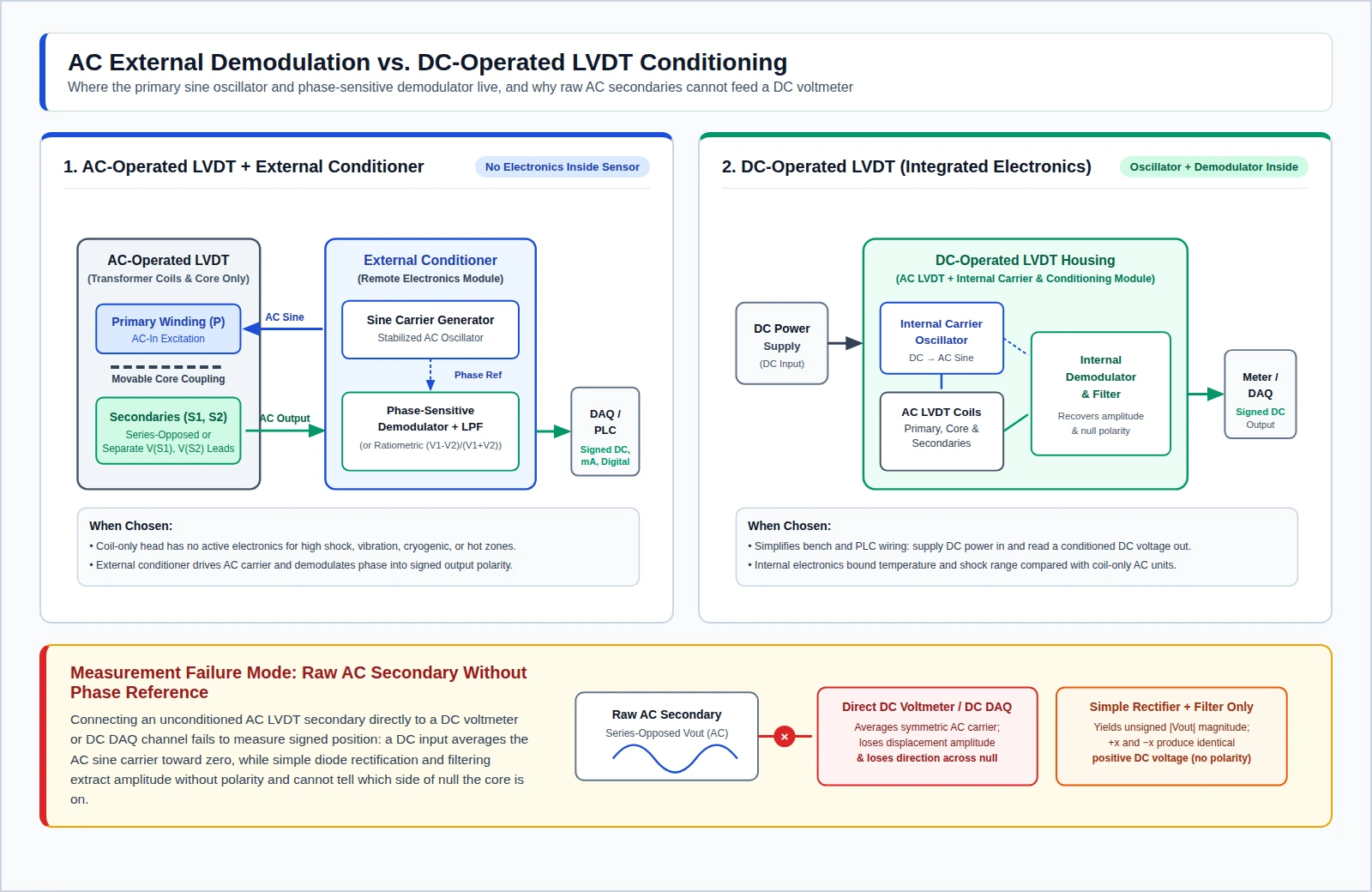
A linear variable differential transformer (LVDT) is an electrical transformer that converts linear displacement from a mechanical null point into a proportional AC signal carrying amplitude for distance and phase for direction, without electrical contact between the moving magnetic core and the coil assembly. Because the sliding core does not touch the inside of the tube, it moves without friction and avoids wiper wear. Driving the center primary coil with AC induces opposing voltages in two series-opposed secondary coils that cancel at the center and reverse phase across null, so a synchronous detector recovers a signed displacement voltage. An AC-operated LVDT contains no internal electronics and pairs with an external conditioner, whereas NewTek’s AC-versus-DC white paper describes a DC-operated LVDT as combining that AC transformer with an internal carrier generator and signal-conditioning module so users supply DC and read a DC position output.
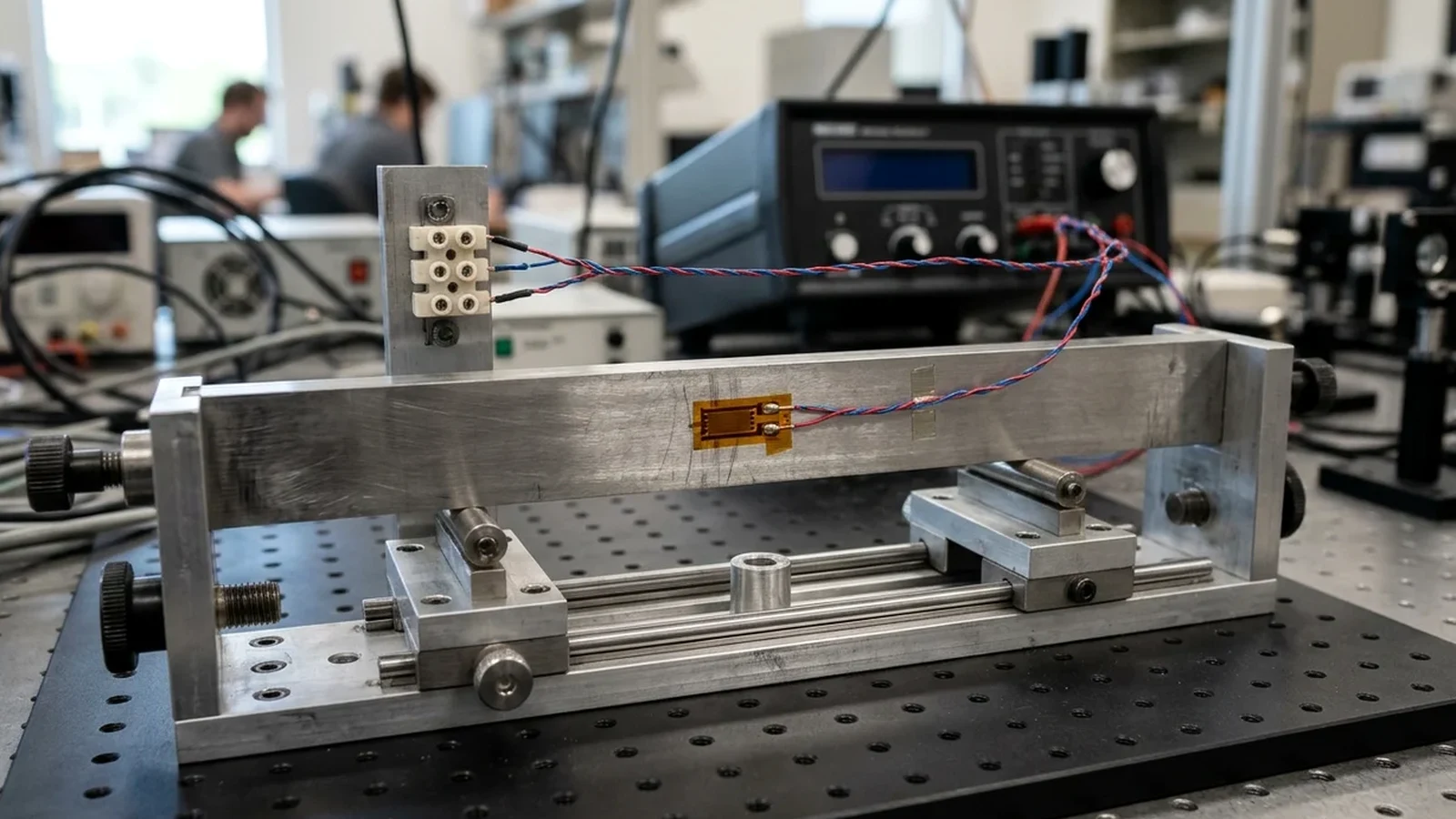
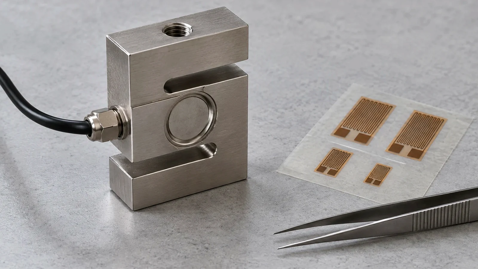
This transducer guide sits in our Sensors and DAQ section alongside our floating DAQ input wiring guide and strain gauge vs load cell comparison.
What is an LVDT and how does it work?
An LVDT sensor is an electromechanical displacement transducer built around three solenoidal coils placed end-to-end around a tube and a movable ferromagnetic core attached by a shaft to the object being measured (Wikipedia LVDT overview, Texas A&M LVDT laboratory manual). NewTek’s LVDT tutorial defines the transducer as a position sensor that converts the linear position or motion of a measured object into a proportional electrical output readable by operators and control systems.
In MIT OpenCourseWare Prelab 3 (Spring 2005, assigned 3/04/05), applying an AC voltage to the center primary coil induces voltages in the two outer secondary coils that are opposite in polarity and proportional to the overlap area between the magnetized core and each secondary coil. As Isaac Choutapalli’s LVDT laboratory sheet, Stanford SSRL’s beamline electronics page, and Texas Instruments application note AN-301 (SNOA606B, January 1982, revised May 2013) each explain, the two matched secondary windings are wired in series opposition so the transducer output equals the voltage difference between them.
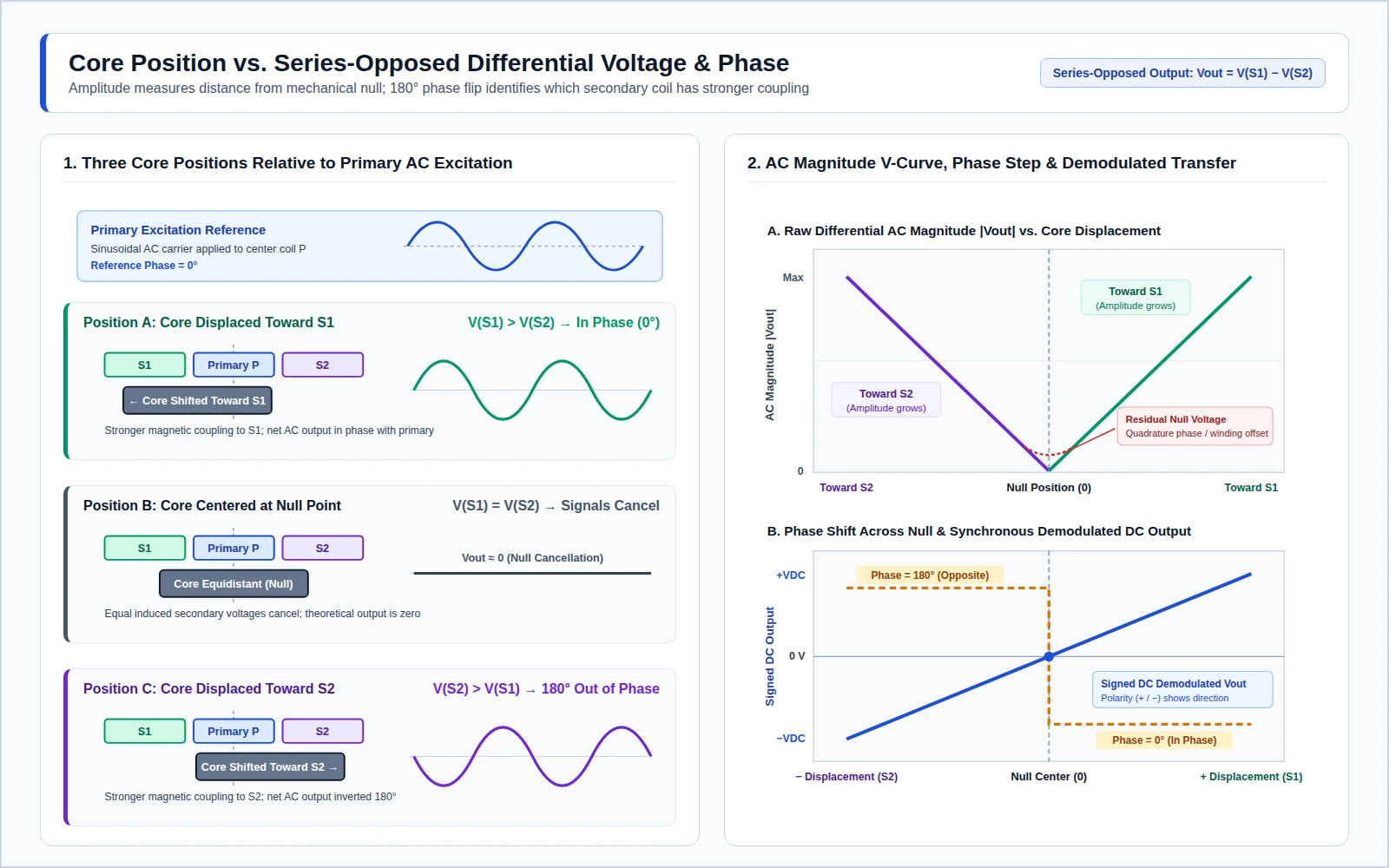
When the core sits at the magnetic and geometric center (the null position), equal voltages are induced in both secondaries and cancel out, making the theoretical differential output zero (MIT OpenCourseWare Prelab 3, Wikipedia). Moving the core toward the first secondary strengthens its magnetic coupling relative to the second secondary, producing a differential AC output in phase with the primary voltage; moving the core toward the opposite secondary shifts the differential output 180 degrees out of phase with the primary (Texas A&M LVDT laboratory manual, Choutapalli LVDT lab sheet). While MIT, Wikipedia, and Texas A&M describe position through induced secondary voltage differences, the University of Utah Mechatronics LVDT manual describes determining core position from the difference between the induced currents in the two detector coils.
Three practical operating characteristics follow directly from this transformer geometry:
- Contactless bore travel: Wikipedia states that because the sliding core does not touch the inside of the tube, it moves without friction and allows a sealed coil assembly with low hysteresis and high repeatability. The University of Utah Mechatronics manual adds that no surfaces are in direct physical contact, so dirt or liquid cannot interrupt a conduction path, there is no wiper wear, drag is minimal, and resolution is limited only by electrical noise. Princeton’s sensor laboratory manual notes that because core and coils do not touch, mechanical friction is limited only to linear bearings where bearings are used. Texas Instruments AN-301 contrasts this zero-friction life against resistive potentiometers.
- Absolute position retention and sum-voltage fault checks: Wikipedia notes that switching power off and restarting leaves the LVDT reading unchanged with no lost positional information, and that under constant excitation voltage the sum of the two secondary voltages stays within a narrow window across the stroke so control hardware can monitor that sum for rapid internal fault detection.
- Residual voltage at null: Real transducers do not reach an exact zero volt null. Ricardo Gutierrez-Osuna’s Intelligent Sensor Systems lecture notes that small variations in the windings leave a small residual output voltage at the central position, while Wikipedia identifies the phase-shift component as quadrature error, which can cause oscillation around null in closed-loop control systems.
Is an LVDT a passive or active sensor?
Engineering references define “passive” and “active” around external excitation rather than assigning a single universal label to the LVDT. In Gutierrez-Osuna’s Intelligent Sensor Systems lecture (Wright State University / Texas A&M University), passive or self-generating sensors directly generate an electrical signal from an external stimulus without an external power supply, with thermocouples and piezoelectric sensors listed as examples. That same lecture defines active or modulating sensors as requiring an external power supply or excitation signal from which output signal power derives, listing thermistors and chemo-resistors as examples without placing the LVDT in either example list.
Instead of relying on a one-word classification, check the two physical facts documented across the transducer sheets:
- An AC-operated LVDT contains no internal electronics inside the coil housing (Wikipedia, NewTek AC-versus-DC white paper), yet its primary winding requires an external AC excitation source to induce secondary voltages through mutual inductance (Choutapalli LVDT lab sheet, Princeton sensor manual).
- DC-operated LVDT versions house integrated oscillators and conditioning electronics inside the sensor body so they run from an external DC supply (Gutierrez-Osuna lecture, NewTek AC-versus-DC white paper).
When do you choose AC external demodulation vs a DC-operated LVDT?
Choose between an AC-operated LVDT with external demodulation and a DC-operated LVDT by deciding whether onboard semiconductor electronics can survive at the measurement point and whether your rack already provides carrier conditioning.
NewTek’s AC-versus-DC white paper notes that because an LVDT is a transformer, it is fundamentally an AC-in, AC-out device: AC-operated units contain no internal electronics, require AC primary excitation, and rely on an external signal conditioner to supply the carrier and demodulate the low-amplitude AC output into DC voltage, current, or digital signals for meters and PLCs. Wikipedia notes that because AC-operated LVDTs contain no electronics, specialized units can be designed to operate at cryogenic temperatures or up to 1200 °F (650 °C), in harsh environments, and under high vibration and shock levels; treat those figures as design capabilities of specialized AC transducers rather than a temperature rating of an arbitrary sensor.
By contrast, NewTek’s white paper and Gutierrez-Osuna’s lecture explain that a DC-operated LVDT packages the AC-operated LVDT together with an integrated carrier oscillator and signal-conditioning module. Users supply DC power and measure a conditioned DC output voltage proportional to core position without external carrier cabling, trading extreme-environment coil-only simplicity for straightforward DC hookup.
Published academic manuals and IC datasheets state different primary excitation frequencies and voltages for their respective hardware, so copy the exact carrier frequency and RMS level from your transducer’s datasheet rather than assuming one universal excitation setting. The only general pacing rule across the manuals comes from Princeton’s sensor manual, which specifies that the excitation carrier frequency should be at least 10 times the frequency of the mechanical motion you wish to record.
| Source document | Stated primary excitation frequency | Stated voltage or circuit context |
|---|---|---|
| Princeton sensor manual | At least 10 times the motion frequency; typical sources in the kHz range (5 kHz oscillation filtered in that lab) | Sinusoidal primary excitation applied to the primary coil |
| Wikipedia LVDT article | Usually in the range 1 to 10 kHz | Alternating current driving the center primary winding |
| Texas A&M LVDT laboratory manual | Typically between 1 kHz and 20 kHz | Usually a sine wave measuring several volts RMS |
| Gutierrez-Osuna lecture | 2 kHz in lecture summary (“Typical LVDTs run at 5V, 2kHz”) | 5 V lecture example |
| NewTek LVDT tutorial (manufacturer note) | Ranging from 1 kHz to 10 kHz in modern LVDTs | Around 3 Vrms in modern LVDTs |
| Texas Instruments AN-301 (SNOA606B) | 2.5 kHz in the application note’s example oscillator | Manufacturer’s specified transducer operating frequency for that example circuit |
| Analog Devices AD598 datasheet | 20 Hz to 20 kHz set by a single external capacitor (400 Hz aircraft power mains also accepted) | Conditioner IC drives an LVDT primary up to 24 V rms and accepts secondaries down to 100 mV rms |
What is the difference between an RVDT and an LVDT?
An LVDT measures linear displacement along a straight axis, whereas its rotary counterpart, the rotary variable differential transformer (RVDT), measures angular displacement of a rotating shaft (Wikipedia LVDT, Choutapalli LVDT lab sheet). When the measurand is force or surface strain rather than linear or rotary displacement, see our strain gauge vs load cell comparison instead.
Electrically, both transducers use contactless electromagnetic coupling between a primary excitation winding and two opposing secondary output windings (Wikipedia RVDT). On an RVDT stator, one secondary coil is in phase with the primary excitation and the second is 180° out of phase. When the rotor directs flux equally into both coils, the secondary voltages cancel at the electrical zero position (E.Z.); rotating the shaft away from E.Z. produces an AC voltage whose magnitude and phase follow the angle and direction of rotation. Because the electrical output format matches an LVDT, Analog Devices specifies in the AD598 datasheet that the AD598 conditioner IC also interfaces to an RVDT.
| Attribute | LVDT (Linear Variable Differential Transformer) | RVDT (Rotary Variable Differential Transformer) |
|---|---|---|
| Measurand | Linear position or displacement along a straight axis | Angular displacement of a rotor shaft |
| Moving element | Cylindrical ferromagnetic core sliding inside a hollow tube | Shaped ferromagnetic rotor turning inside a wound stator |
| Null reference | Central null position where series-opposed secondaries cancel | Electrical zero position (E.Z.) with equal flux in both secondaries |
| Operating span | Linear stroke specified on the transducer’s calibration certificate | Wikipedia notes theoretical operation within ±45°, accuracy dropping quickly past ±35°, operational limits mostly within ±30°, and some designs up to ±40° |
| Sensor named for that axis | Potentiometric sensor or an LVDT | RVDT, or an encoder that generates a TTL-level pulse train (Choutapalli LVDT lab sheet) |
How do you wire an LVDT sensor and signal conditioner?
Wire an LVDT and its signal conditioner according to the transducer’s lead diagram and the conditioner’s detection method, because LVDTs have no universal wire-color code or universal connector pinout. For example, Stanford SSRL’s beamline electronics page documents a 6-pin PT02A-10-6P connector on its GHSA 750 series LVDT cable, which applies specifically to that beamline assembly rather than LVDTs from other series.
At the circuit level, external AC conditioning splits into two wiring and demodulation architectures:
- Series-opposed secondary wiring with phase-sensitive synchronous demodulation: When the two secondary windings are connected in series opposition internally or at the terminal strip, the primary takes two AC excitation leads and the combined secondary pair delivers the difference voltage Vout (Wikipedia, Princeton sensor manual, Texas Instruments AN-301). As Texas Instruments AN-301 states, rectifying and filtering that AC signal yields amplitude information only; phase-sensitive demodulation is needed to recover both amplitude and the polarity showing which side of null the core occupies. In Choutapalli’s LVDT lab sheet and Princeton’s sensor manual, synchronous demodulation multiplies or switches the secondary wave against the primary sine so in-phase signals produce a positive product and 180-degree out-of-phase signals produce a negative product before a low-pass filter strips the carrier. By contrast, a plain diode-rectifier demodulator like the student circuit in the University of Utah Mechatronics manual produces an unsigned DC voltage magnitude without null-crossing sign.
- Separate secondary leads with ratiometric conditioning: Conditioners such as the Analog Devices AD598 bring both secondary voltages into the chip separately and compute the ratio of their difference to their sum. Because synchronous detection is not employed, the AD598 datasheet notes that the circuit has no sensitivity to phase shift between primary excitation and secondary outputs, aligning with amplitude-extraction approaches noted in Texas Instruments’ Analog Applications Journal where measured amplitude is not influenced by primary-to-secondary phase shift. However, the AD598 datasheet cautions that ratiometric operation requires the sum of the secondary voltages (VA+VB) to remain constant across the LVDT stroke; if an LVDT’s secondary sum varies with stroke length, output nonlinearity results.
Once your external conditioner or DC-operated LVDT delivers a conditioned DC voltage to a differential analog input on a data-acquisition board, verify whether that output is isolated or earth-referenced and apply the bias-return and common-mode checks in our floating DAQ input wiring guide.
How are LVDT sensors installed inside hydraulic cylinders?
Hydraulics and mechanical assemblies use LVDTs (Texas A&M LVDT laboratory manual), while Texas Instruments’ Analog Applications Journal says LVDTs measure the position of linear actuators such as industrial hydraulic valves and aircraft control surfaces. In NASA Tech Briefs Document ID 19850000518 (published March 1, 1986), an integral LVDT is mounted coaxially and contained completely inside the cylinder of a hydraulic actuator, providing continuous, stepless readout of piston position relative to the cylinder for computer motion control where external mounting space is minimal.
Because the NASA Technical Reports Server citation page states that there are no available downloads for that record, it does not publish a general cylinder machining print, bore diameter, or pressure rating. For any internal or external actuator mount, get housing pressure ratings and thread dimensions from the specific cylinder-rated LVDT drawing, and align the core rod coaxially with the coil bore so the moving core travels without rubbing the inside of the tube (Wikipedia, University of Utah Mechatronics manual, NASA Document ID 19850000518).
How do you calibrate an LVDT displacement sensor?
Calibrate an LVDT system by stepping the core through known reference displacements across its certified range, recording the conditioned output voltage at each stop, and fitting voltage against displacement (University of Utah Mechatronics manual, Choutapalli LVDT lab sheet). Texas A&M’s LVDT laboratory manual notes that each LVDT ships with a calibration certificate showing its linearity and operating range, which defines the stroke span you verify on the bench.
- Step through reference positions with a micrometer: In Choutapalli’s LVDT calibration procedure, you rotate a micrometer stage by 2 mm, record the conditioned DC output voltage, repeat at every 2 mm step until the LVDT core fully contracts, plot the calibration curve of voltage versus displacement, and repeat the entire run with a second operator to verify repeatability.
- Fit the calibration curve model: NIST’s Engineering Statistics Handbook Section 2.3.6.1 notes that several calibration curve models can be considered for instrument calibration, including the straight-line linear instrument model Y = a + bX.
- Watch end-of-stroke sensitivity shifts and the reported phase difference: Published NIST measurements show why single-number slope assumptions fail near stroke extremes or higher motion frequencies. In a NIST cryogenics piston-velocity paper (2012), researchers calibrated the LVDT on linear compressor #1 in house and found an average sensitivity of 19.8±0.1 mm/V across its 10 mm stroke, while sensitivity changed by about ±1.2 mm/V over the last 20% of full stroke. On that same compressor #1 setup, velocity amplitudes from back-EMF and the LVDT agreed within 7%, and LVDT phase agreed within 2° of back-EMF at 16 Hz but led as frequency increased, reaching a 30° difference at 60 Hz. At nanometer scales, NIST’s stylus profilometer uses an LVDT height-detection mechanism to calibrate 7 nm step heights with angstrom-level uncertainties.
LVDT selection, wiring, and coaxial mounting checklist
Use the verification table below to record your transducer’s certificate stroke, conditioning topology, secondary hookup, carrier pacing, and coaxial alignment before commissioning a channel. Manufacturer specifications referenced in prose include Texas Instruments application note AN-301 (SNOA606B), Texas Instruments’ Analog Applications Journal note on LVDT amplitude demodulation, the Analog Devices AD598 datasheet, and NewTek Sensor Solutions’ LVDT tutorial and AC-versus-DC white paper.
| Verification item | Engineering rule and source condition | What to check on your setup |
|---|---|---|
| AC external conditioner or DC-operated LVDT | AC LVDTs have no internal electronics and pair with an external conditioner; DC-operated LVDTs integrate a carrier generator and conditioning module (NewTek white paper, Wikipedia) | Confirm ambient temperature, shock, and whether DC supply-and-readout simplicity outweighs coil-only packaging |
| Primary excitation source | External conditioner generates a stabilized sine wave for AC LVDTs (Choutapalli LVDT lab sheet, AN-301), or internal oscillator generates it inside a DC-operated LVDT (Gutierrez-Osuna lecture) | Match RMS excitation voltage and frequency to the transducer datasheet |
| Secondary winding hookup | Series-opposed pair outputs the difference between the top and bottom secondary voltages (Wikipedia, SSRL); ratiometric chips like the Analog Devices AD598 take separate secondaries and require constant VA+VB across stroke | Copy terminal pins from your specific sensor sheet; do not assume universal wire colors |
| Direction recovery across null | Phase-sensitive synchronous demodulation recovers signed polarity across the 180° null phase shift; plain rectification yields unsigned amplitude only (AN-301, Princeton sensor manual) | Verify signed positive and negative DC transition across mechanical null before connecting to a control loop |
| Carrier-to-motion bandwidth ratio | Carrier frequency should be at least 10 times the highest recorded motion frequency (Princeton sensor manual) | Record exact carrier frequency from the sensor datasheet and verify low-pass filter cutoff |
| Hydraulic cylinder integration | NASA Tech Briefs Document ID 19850000518 describes an integral LVDT mounted coaxially and contained completely inside a hydraulic actuator cylinder | Apply in-cylinder mounting only with a purpose-built coaxial actuator LVDT and manufacturer mechanical drawings |
| Calibration range and curve | Step through known displacements (such as 2 mm micrometer increments in Choutapalli’s LVDT lab sheet), plot voltage versus displacement, and check end-of-stroke linearity against the calibration certificate (Texas A&M LVDT manual) | Keep operating travel inside the linear stroke printed on the sensor’s calibration certificate |
| Bore clearance and coaxial alignment | Sliding core moves inside the bore without physical contact or wiper wear (Wikipedia, University of Utah Mechatronics manual) | Align core extension shaft coaxially so the core does not rub the coil bore throughout full travel |