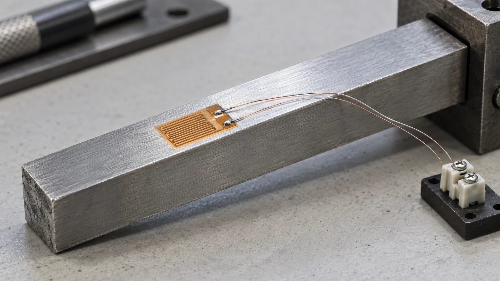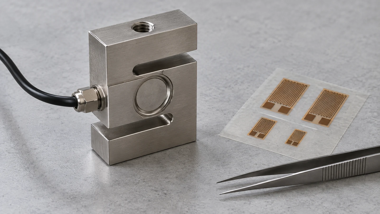
Buying bare strain gauges when you need a calibrated force reading creates rework: you take on the bonding, wiring and calibration that a finished load cell already includes. A strain gauge is a component that senses surface strain; a load cell is a calibrated transducer that turns load into an output, and the most common type uses strain gauges in a bridge on a machined metal body.
This comparison is compiled from standards and public references by an independent publication (about this site).
If you are choosing a sensor to measure force or weight, start with a load cell; choose bare strain gauges only when you need strain on the surface of your own part. ASTM E251, the test method for metallic bonded strain gauges, explicitly excludes transducers such as load cells and extensometers that use strain gauges as sensing elements, which is the clearest statement that the two are different products. OIML R 60-1:2021 defines a load cell as a measuring transducer that produces an output in response to an applied load. For displacement use an LVDT, for specimen elongation an extensometer, and for fluid pressure a pressure transducer.
Quick specs: what you need to measure, and where to start.
| Input or item | Typical value or source | Why it matters |
|---|---|---|
| Force or weight on a load path | Strain-gauge load cell, rated in mV/V; a full-bending bridge built for 1000 µε at rated load gives 2 mV/V (Micro-Measurements) | Gives a calibrated force output without bonding work |
| Strain on the surface of your own part | Bonded strain gauge; foil gauges 120, 350 or 1000 Ω are most common (Acromag) | Measures local strain where the load path is your structure |
| Elongation of a test specimen | Extensometer, verified and classified under ASTM E83 | Reports elongation between defined gauge points |
| Linear position or displacement | LVDT (differential transformer) | No contact between core and coil; absolute position |
| Fluid pressure | Pressure transducer; strain-gauge and piezoresistive types use a diaphragm and bridge | Packaged sensing for liquids and gases |
| Bridge sensitivity | About 0.5 µV/V per µε × N at gauge factor 2.0; N = 1 for a quarter bridge, 4 for a full-bending bridge (Micro-Measurements) | Sets how much amplification you need |
Is a load cell just a strain gauge?
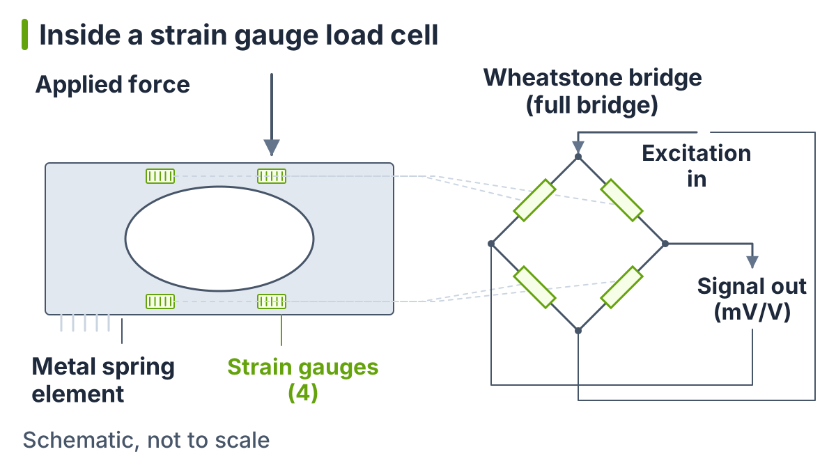
No. OIML R 60 defines a load cell as a measuring transducer that produces an output in response to an applied load, and notes that principles other than strain gauges exist. In the common strain-gauge type, which this article compares, a manufacturer’s description (LCM Systems) lists a metal spring element, foil gauges bonded where it strains, usually four gauges in a Wheatstone bridge, and protective coatings or enclosures. A strain gauge on its own is a resistor that changes with the strain of whatever it is bonded to.
| Question | Bare strain gauge | Strain gauge load cell |
|---|---|---|
| What it measures | Strain on the part it is bonded to | Force or weight through its own body |
| What you must add | Surface preparation, adhesive, wiring, bridge completion, temperature compensation, calibration | Signal conditioning and system calibration |
| Calibration | Gauge factor per lot; your installation is not calibrated in force | Rated output in mV/V from the maker’s calibration |
| Reuse | Normally cannot be moved once bonded (ASTM E251) | Can be moved between fixtures |
| Standards context | ASTM E251 test methods for gauge characteristics | OIML R 60 accuracy classes A, B, C and D for load cells in legal weighing |
Strain gauge theory, including how the gauge factor links resistance change to strain, is covered in our strain gauge explainer, which also draws the quarter, half and full bridge layouts used inside load cells.
Takeaway: Buy a load cell when the measurand is force; bond gauges only when the measurand is strain in your own structure.
How do the six sensor types compare?
They measure different quantities, so the first cut is by measurand, not by accuracy figure. The table puts six types on the same dimensions.
| Sensor | Measures | Sensing principle | Typical output | Typical use | Verification reference |
|---|---|---|---|---|---|
| Strain gauge | Surface strain (ΔL/L) | Resistance change of a bonded grid | ΔR/R, read through a bridge | Stress analysis on parts | ASTM E251 (gauge characteristics) |
| Load cell | Force or weight | Most often strain gauges on a spring element; other principles exist | mV/V at rated load (strain-gauge type) | Scales, hoppers, test rigs | OIML R 60 for legal weighing; system calibration |
| Force sensor / transducer | Force | Often strain gauges; other principles exist | mV/V or amplified | Test and process force | Calibration against force standards |
| Extensometer | Elongation between gauge points | Contact (clip-on) or non-contact | Displacement or strain signal | Tensile and compression tests | ASTM E83 classes |
| LVDT | Linear displacement | Differential transformer with moving core | AC, or DC with built-in electronics | Position, gauging | Displacement calibration |
| Pressure transducer | Fluid pressure | Often strain gauges or piezoresistors on a diaphragm | mV/V or amplified | Hydraulics, process lines | Pressure calibration |
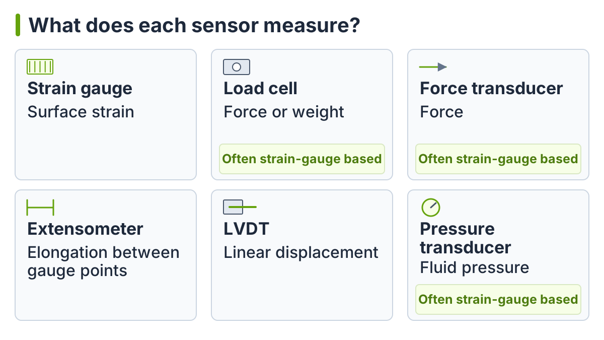
Vendors use “load cell”, “force sensor” and “force transducer” for overlapping products. Check the measurand, range, output and calibration on the datasheet rather than the product name. For non-contact dimensional sensors, which sit outside this table, see our profileGAUGE C.ODC specs reading.
Takeaway: Pick the row by what you need to measure, then compare products within that row.
Strain gauge or extensometer for a tensile test?
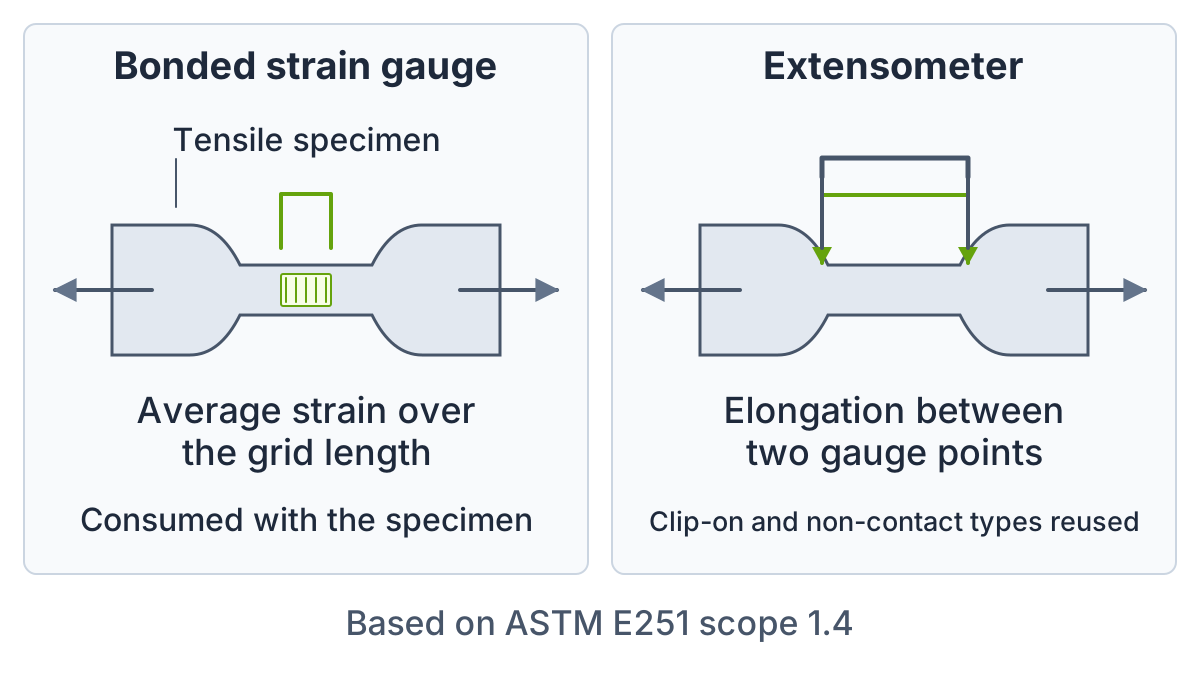
Use an extensometer when the test standard asks for elongation between defined gauge points, and bonded gauges when you need local strain at a specific spot. ASTM E251 states the difference directly: bonded gauges measure average unit elongation over their own gauge length, while extensometers measure total elongation between definite gauge points.
| Point | Bonded strain gauge | Extensometer |
|---|---|---|
| What it reports | Average strain over the grid length | Elongation between gauge points |
| Reuse | Consumed with the specimen | Clip-on and non-contact types are reused; follow the model’s instructions |
| Verification | Gauge characteristics per ASTM E251; cannot be verified with E83 apparatus | Classified by error under ASTM E83 |
| Strength | Local strain at a chosen spot and direction | Test-standard elongation and modulus over a gauge length |
If local strain is what you need, our explainer covers gauge length and rosette choices for that job.
Common mistake: Bonding one strain gauge to a tensile specimen and reporting its reading as the specimen’s elongation. The gauge reports local strain over a few millimetres, not elongation over the standard’s gauge length.
Takeaway: Follow the test standard’s definition of elongation; it usually points to an extensometer.
Where do LVDTs and pressure transducers fit?
An LVDT measures position, not force or strain, and a strain-gauge or piezoresistive pressure transducer packages strain sensing behind a diaphragm. An LVDT is a transformer with one primary and two secondary coils; a moving core changes the coupling, and the differential output tracks the core position without contact between core and coil.
Strain-gauge and piezoresistive pressure transducers use the principle you already know: gauges or piezoresistors on a diaphragm, wired as a Wheatstone bridge. Whether one conditioner can serve both a load cell and a pressure transducer depends on excitation, input range, bridge wiring and output type; check both datasheets before planning to share it. How these signals then reach a controller or network is covered in our guide to industrial IoT sensors and interfaces.
Takeaway: Choose an LVDT for displacement and a pressure transducer for fluid pressure, even when a load cell could be rigged to infer either.
The 4-question sensor choice
Settle the measurand, whether a sensor can sit in the load path, the range and environment, and the output and calibration needed, in that order; each answer narrows the next.
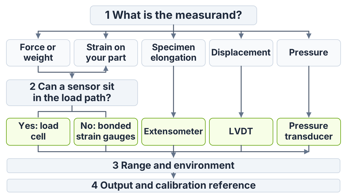
- What is the measurand? Force, weight, strain, elongation, displacement or pressure. This picks the row in the comparison table.
- Does the load pass through your own part? If you must measure strain in your structure, bond gauges; if you can put a sensor in the load path, use a load cell.
- What range and environment? Capacity, overload, temperature and sealing narrow the product list.
- Which output and calibration do you need? A raw mV/V bridge, an amplified signal or a digital or networked interface; and the calibration reference your report must cite. Machine and test-rig integration topics are collected under automation.
Common mistake: Choosing by accuracy class before the measurand is fixed. A Class C load cell is the wrong answer to a strain question, whatever its specification.
Takeaway: Answer the four questions in writing before you open a catalog.
What signal and calibration does each sensor need?
Bridge-based sensors produce a few millivolts and need excitation and amplification; verification documents differ by sensor type and use. At a gauge factor of 2.0, Micro-Measurements gives bridge output as about 0.5 µV per volt per microstrain × N: N = 1 for a quarter bridge and 4 for a full-bending bridge, while an axial (Poisson) full bridge gives N = 2 + 2ν. Keep three things apart in the table below: the reference document, an accuracy class, and the calibration certificate of your own instrument.
| Sensor | Signal you get | What to add | Verification or calibration document |
|---|---|---|---|
| Strain gauge, quarter bridge | ΔR/R of about 0.6% at 3000 µε (120 Ω, GF 2.00; Acromag) | Bridge completion, excitation, amplifier, temperature compensation | Gauge factor from the gauge lot; shunt or system calibration |
| Load cell (strain-gauge type) | Rated mV/V; example, assumed inputs: 2 mV/V at 10 V excitation gives 20 mV at rated load | Excitation within the model’s limit, bridge amplifier or bridge ADC | Maker’s calibration certificate; OIML R 60 class where legal weighing applies |
| Force transducer | mV/V or amplified, by model | As for load cells, or per amplified output | Calibration certificate; ASTM E4 verification when part of a testing machine |
| Extensometer | Displacement or strain signal | Conditioner matched to its type | Verification and classification per ASTM E83 |
| Pressure transducer | mV/V (bridge types) or amplified | Excitation and conditioning per datasheet | Pressure calibration certificate |
| LVDT | AC differential voltage | Demodulator, unless built in | Displacement calibration |
If you are planning the acquisition side, our sensors and DAQ section collects related explainers, and the test and measurement section covers instrument specifications such as resolution versus accuracy.
Takeaway: Budget for excitation, amplification and a named calibration reference along with the sensor itself.
When does this not apply?
This comparison does not cover:
- Dynamic bandwidth; piezoelectric force sensors and high-frequency measurement are outside its scope.
- Torque and rotating-shaft measurement.
- Legal-for-trade acceptance, which follows the rules of your jurisdiction in addition to OIML R 60.
- Dimensional gauges that measure size rather than strain (as distinct from optical extensometers).
Takeaway: If your task falls in one of these areas, use this page only for the measurand split and look for a specialist source.
Related reading
Next reads, depending on the sensor you chose:
- Strain gauge basics — Work through gauge factor, gauge types and bridge wiring.
- Industrial IoT sensors — Choose outputs and networks once the sensor type is fixed.
- profileGAUGE C.ODC specs — See how a non-contact gauge states resolution, repeatability and linearity.
Takeaway: Read the strain gauge basics next if you chose bonded gauges.
Method and update log
First published 7 October 2026 with the six-sensor comparison, the 4-question selection and the signal and verification table. Compiled from the scope sections of ASTM E251, E83 and E4, OIML R 60-1:2021, manufacturer technical material from Micro-Measurements, Acromag and LCM Systems, and general encyclopedia references, which are marked as such in the sources. No sensors were tested for this article. This site is independent of the manufacturers it cites; see about this site. Last reviewed 7 October 2026.