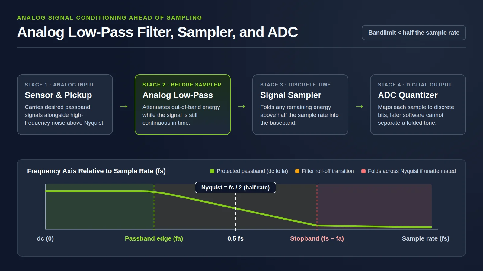
Put an analog low-pass filter ahead of the ADC. Sampling folds energy above half the sample rate into the recorded band, and a later digital filter cannot separate that fold from a real tone. Set the passband on the highest frequency you need and the stopband on the first frequency that folds into it. Steeper roll-off adds ringing and delay.
This site (Maximizing Value at NI) is not National Instruments and not Emerson. Related guides in Sensors and DAQ cover DAQ sample-rate planning for per-channel conversion budgets and raw file sizes, and strain-gauge amplifier signal-conditioning bandwidth for bridge excitation and gain.
What is aliasing in an ADC?
An alias is a false lower-frequency component that appears in sampled data acquired at too low a sampling rate, as defined in Lehigh University’s anti-alias filter lecture handout. In Wikipedia’s aliasing overview, aliasing occurs when a signal reconstructed from samples contains low-frequency components not present in the original signal because original components exceed the Nyquist frequency, fs/2, where fs is the sampling frequency. Aliases are frequency components that produce the identical sample after sampling.
In Wikipedia’s audio example, when a signal is sampled at 32,000 samples per second, any frequency components at or above 16,000 Hz (the Nyquist frequency for that rate) cause aliasing. Those high frequencies appear as lower frequencies in the recorded digital sample and cannot be reproduced by the DAC. As Wikipedia’s Nyquist–Shannon sampling theorem article notes, undersampling that causes aliasing is not in general a reversible operation.
Wikipedia’s sampling figure illustrates a single sinusoid at 0.6 fs sharing samples with aliases at 0.4 fs, 1.4 fs, and 1.6 fs. A separate sawtooth example in the same article uses a 22050 Hz sampling rate whose Nyquist frequency is 11025 Hz = 22050 Hz / 2. Analog Devices tutorial MT-002 shows that in the time domain, samples produce an aliased sinewave at fs − fa, while in the frequency domain, sampler images appear at |± K fs ± fa| for K = 1, 2, 3, 4, and so on across Nyquist zones of width 0.5 fs.
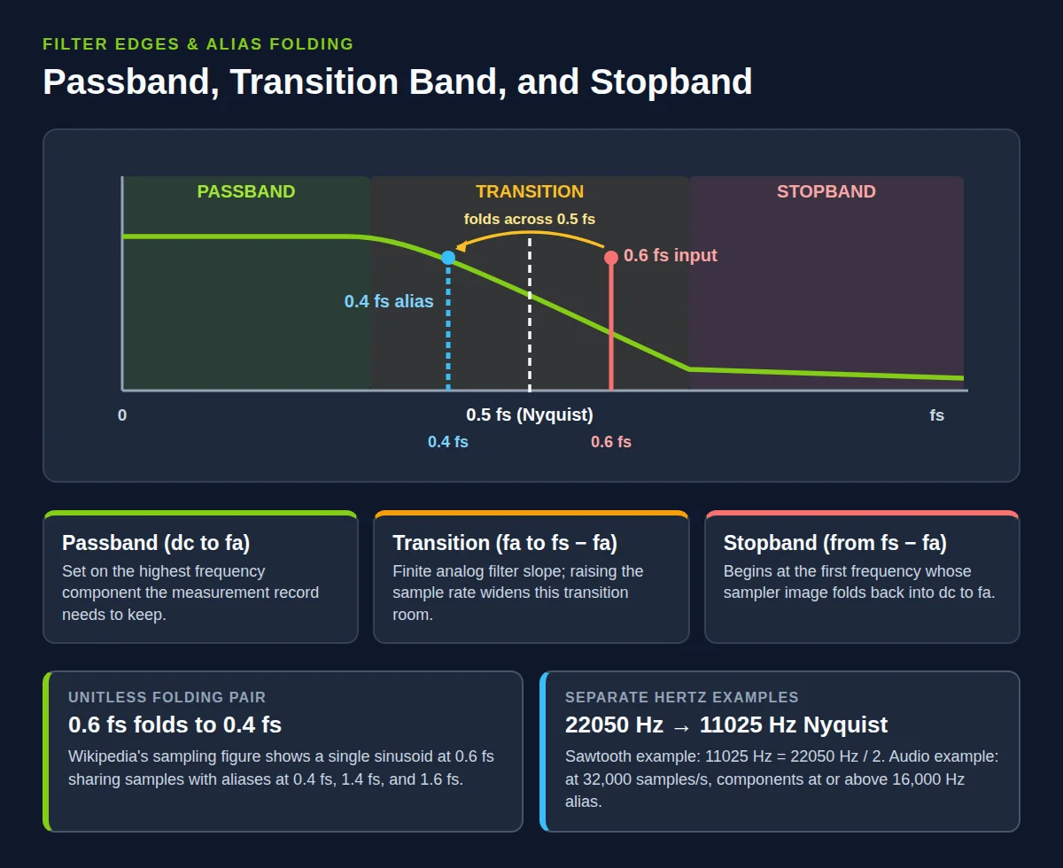
Takeaway: Aliased tones produce the identical samples as real in-band tones, so post-capture software cannot separate them.
Why does the analog filter have to come before the converter?
In Princeton Sound Lab’s sensor tutorial, the Nyquist criterion dictates bandlimiting all signals to less than half the sampling rate, and broad-spectrum signals require an analog lowpass filter before the data acquisition system. Lehigh’s handout places that analog anti-alias filter between the sensor and the A/D converter so higher-frequency noise is reduced before sampling modulates it to a lower frequency.
National Instruments, in Anti-Aliasing Filters and Their Usage Explained, notes that even when a measured signal has an upper frequency limit, stray pickup from the powerline frequency or local radio stations can contain frequencies above the Nyquist frequency that alias into the measurement range. Adding a low-pass filter before the sampler and the ADC prevents those components from being sampled; because this stage precedes the sampler and ADC, the filter is an analog filter.
Similarly, Wikipedia’s anti-aliasing filter article defines an anti-aliasing filter as a filter placed before a signal sampler to restrict signal bandwidth over the band of interest. While unambiguous reconstruction is possible when power above the Nyquist frequency is zero, a brick-wall filter is idealized and impractical, so a practical anti-aliasing filter trades reduced bandwidth against increased aliasing. Julius O. Smith’s Sampling Theorem note at Stanford CCRMA shows that exact reconstruction holds when the continuous-time spectrum is zero at and above pi divided by the sampling period, making the sample spectrum match the continuous-time spectrum between plus and minus half the sampling rate.
Analog Devices MT-002 adds that full-scale components above fs − fa alias into dc to fa, become indistinguishable from actual signals, and limit dynamic range to the stopband attenuation DR. Likewise, Wikipedia’s quantization article notes that any distortion created after the anti-aliasing filter will alias back into the band of interest if it sits above 1/2 the sample rate.
Common mistake: Digitizing an unfiltered broadband sensor channel first and applying a digital low-pass filter later. Once out-of-band energy folds into the stored samples, digital filtering cannot distinguish the alias from a true signal.
Where do cutoff and stopband sit against the sample rate?
To reconstruct a bandlimited signal free of aliasing, the sampling rate must be at least twice the signal bandwidth; for a sample rate fs, perfect reconstruction is guaranteed for a bandlimit B < fs/2. Analog Devices MT-002 points out that specifying the antialiasing filter at fs/2 assumes the band of interest extends from dc to fs/2, which is rarely the case. Instead, MT-002 defines the transition band from the passband corner frequency fa to the stopband frequency fs − fa, with desired stopband attenuation DR.
National Instruments calls the span between f1 and f2 the transition band, noting that an ideal filter passing all frequencies below f1 and cutting off all frequencies above f1 is not physically realizable. Because signals inside the transition band can still cause aliasing, in practice the sampling frequency should exceed two times the highest frequency in the transition band.
On Wikipedia’s anti-aliasing filter page, CD audio filters the signal to a 20 kHz passband edge with a 22.05 kHz stopband Nyquist frequency at a 44.1 kHz sample rate, leaving a narrow 2.05 kHz transition band that trades filter complexity against performance. Separately, National Instruments’ audio example cites components up to 20 KHz, a 40 Khz Nyquist rate, a 20 KHz cutoff, and a practical sampling frequency from 44.1 KHz to 96 KHz to allow a transition band of at least 2 KHz. Sampling higher than a perfect filter would theoretically require is called oversampling, which leaves room for that transition band.
Texas Instruments application note SBAA282B illustrates a converter cookbook case using the ADS8319 at 500 ksps (a 250 kHz Nyquist frequency), where a passband flatness guideline sets the cutoff one decade above a 5 kHz input at 50 kHz while Nyquist remains 250 kHz. In a separate Texas Instruments note, SLYT626, a 1 kHz maximum input is sampled at 100 kHz rather than a 10 kHz ten-times preference, placing Nyquist at 50 kHz where that low-pass filter is down by approximately 50 dB.
How deep is the stopband for a 16-bit converter?
An analog-to-digital converter acts as a quantizer. In the ideal ADC model on Wikipedia’s quantization page, quantization error is uniformly distributed between −1/2 LSB and +1/2 LSB when the signal covers all quantization levels, and the potential signal-to-quantization-noise power ratio changes by approximately 6 dB per bit.
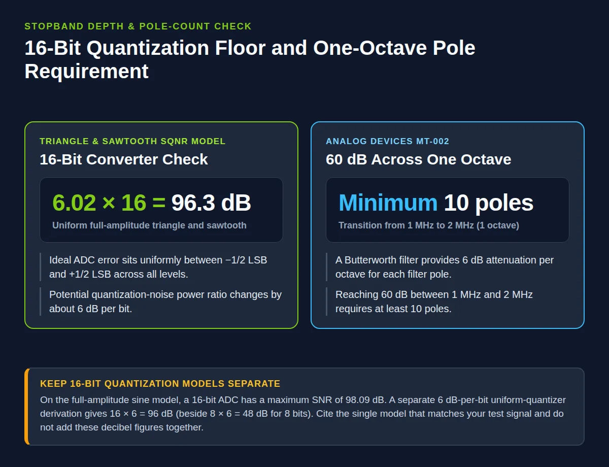
For a uniform full-amplitude triangle and sawtooth waveform, Wikipedia states that SQNR is approximately 6.02 times Q dB, giving a 16-bit ADC a maximum signal-to-quantization-noise ratio of 6.02 × 16 = 96.3 dB. For a full-amplitude sine wave, SQNR is approximately 1.761 + 6.02 times Q dB, giving a 16-bit ADC a maximum signal-to-noise ratio of 98.09 dB. A separate uniform-quantizer derivation later in the same article gives SQNR = 8 × 6 = 48 dB for 8 bits and SQNR = 16 × 6 = 96 dB for 16 bits. Keep those three 16-bit figures separate rather than combining them.
Princeton’s sensor tutorial relates required stopband attenuation to the ADC bit count B so the analog filter brings out-of-band sensor energy down to the minimum noise level inherent in sampling. In Texas Instruments SBAA282B, the design objective attenuates alias signals to one-half LSB of the ADC: for a 1 mV input at 250 kHz against a calculated 1/2 LSB = 38.14 µV at 250 kHz, AC simulation shows −33.43 dB attenuation at Nyquist, lowering the input alias to 21.3 µV. Analog Devices MT-002 adds a pole-count check: a Butterworth filter provides 6 dB attenuation per octave per pole, so achieving 60 dB attenuation across the single octave from 1 MHz to 2 MHz requires a minimum of 10 poles.
How do Butterworth and Bessel filters trade roll-off for ringing and delay?
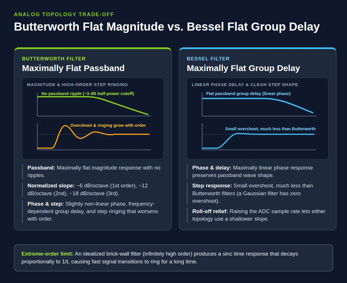
As Wikipedia’s Butterworth filter article explains, a Butterworth filter is a maximally flat magnitude filter designed for a passband frequency response with no ripples that rolls off toward zero in the stopband. Its normalized cutoff sits at the half-power point of approximately −3 dB, corresponding to a voltage gain of 1/√2 ≈ 0.7071. Normalized low-pass slope is −6 dB per octave (−20 dB per decade) for first order, −12 dB per octave for second order, and −18 dB per octave for third order.
That steep magnitude transition carries time-domain costs. Wikipedia notes considerable overshoot and ringing in the Butterworth step response that worsens with increasing order, alongside a slightly non-linear phase response and largely frequency-dependent group delay. In the extreme case described by Princeton Sound Lab, an infinitely high-order brick-wall filter produces a sinc time response decaying proportionally to 1/t, causing rapidly changing signals to ring for a long time. Non-linear phase also creates unequal group delay across frequency so higher-frequency signals arrive later than low-frequency signals; linear-phase filters reduce this phase distortion.
By contrast, Wikipedia’s Bessel filter article defines a Bessel filter as an analog linear filter with maximally flat group delay (maximally linear phase response), preserving the wave shape of filtered passband signals. A Bessel filter exhibits a small step-response overshoot that is much less than Butterworth filters, while a Gaussian filter has zero overshoot. Texas Instruments SBAA282B frames filter selection directly as a choice between Bessel and Butterworth topologies, and Princeton notes that raising the ADC sampling rate lets either filter use a more shallow roll-off for a better time response.
When does oversampling relax the analog filter?
Princeton Sound Lab notes that increasing the ADC sampling rate allows the anti-aliasing filter to use a higher cutoff frequency and a more shallow roll-off while still eliminating aliasing. Both Wikipedia’s sampling-theorem article and anti-aliasing filter article describe this oversampling margin as leaving room for a practical transition band so all frequencies of interest can be reconstructed.
In Wikipedia’s delta-sigma modulation article, delta-sigma modulation is described as an oversampling method that encodes an analog input into a low-bit-depth digital stream at a very high sample frequency before a digital filter demodulates it to a high-bit output at a lower sampling frequency. Oversampling reduces the steepness requirement for the analog low-pass anti-aliasing filter ahead of the modulator. Afterward, the digital decimation filter cuts high-frequency noise across the band of interest and lowers the sampling rate, though it cannot remove an alias that already folded into the passband at the modulator input.
Analog Devices tutorial MT-022 confirms that oversampling relaxes the requirements on the analog antialiasing filter, and that decimation causes no loss of information provided the decimated output data rate exceeds twice the signal bandwidth. MT-022 also notes that a perfect classical N-bit sampling ADC with a full-scale sinewave input has an SNR of (6.02N + 1.76) dB, which is the sine-input formula rather than the 96.3 dB triangle-and-sawtooth figure.
What should you record on the channel filter checklist?
| Channel parameter | Engineering rule to record |
|---|---|
| Protected passband (fa) | Highest signal frequency component the measurement record needs to keep |
| Stopband start (fs − fa) | First frequency whose sampler image folds back into dc to fa |
| Sampling rate (fs) | Above twice the signal bandwidth, with room for the analog transition band |
| Stopband attenuation target | Named quantization model (such as 96.3 dB triangle/sawtooth or 98.09 dB sine for 16 bits) or half-LSB goal |
| Analog filter family | Butterworth for maximally flat passband magnitude, or Bessel for flat group delay and passband wave shape |
| Oversampling relief | Higher ADC sample rate or delta-sigma modulation when a gentler analog slope is needed |
Use our DAQ sample-rate planning worksheet to size multi-channel conversion limits, record duration, and raw file bytes, and see strain-gauge amplifier signal-conditioning bandwidth for bridge excitation and amplifier gain checks.