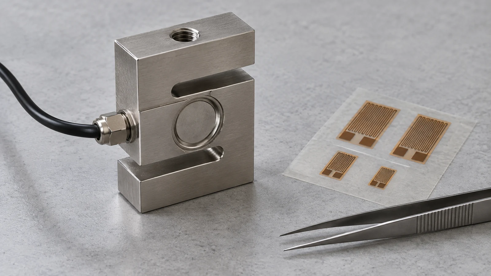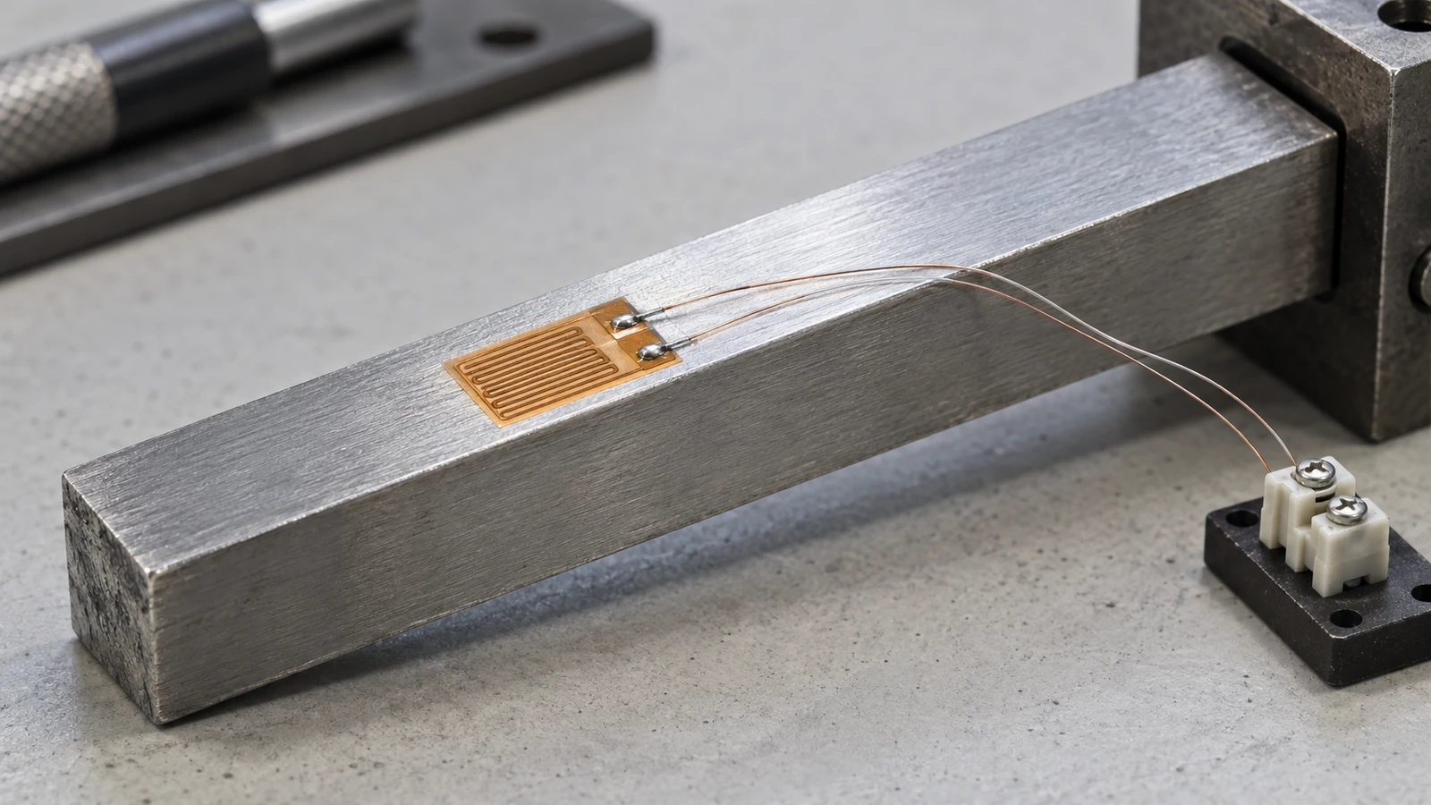
Using the nominal gauge factor of 2 instead of the value stated for your gauge lot builds a wrong scale factor into every reading. A strain gauge is a fine resistor grid bonded to a surface; when the surface stretches, the grid’s resistance rises in proportion, ΔR/R = GF × ε, and a Wheatstone bridge turns that small change into a voltage you can measure.
A strain gauge measures strain, the fractional change in length (ΔL/L), averaged over its own grid length; ASTM E251 describes it that way and calls the gauge factor its transfer function. Metal foil gauges, the general-purpose type, have a gauge factor a little over 2, so 1,000 microstrain changes resistance by about 0.2%. Because the change is that small, gauges are read in a bridge: at a gauge factor of 2.0 the output is about 0.5 µV per volt of excitation per microstrain times a factor N, which is 1 for a quarter bridge and 4 for a full-bending bridge whose arms add.
Key facts at a glance:
| Item | Typical value or source | Why it matters |
|---|---|---|
| Measurand | Strain ε = ΔL/L, averaged over the grid (ASTM E251) | Sets what a gauge can and cannot report |
| Gauge factor, metal foil | A little over 2 (e.g. 2.09–2.12 in university lab gauges) | Converts ΔR/R into strain |
| Nominal resistance | 120, 350 or 1000 Ω most common (Acromag) | Must match the instrument’s bridge completion |
| Bridge output | ≈ 0.5 µV/V per µε × N at GF 2.0; N = 1 quarter bridge, 4 full-bending bridge, 2 + 2ν axial (Poisson) full bridge (Micro-Measurements) | Sets the amplification you need |
| Biggest error to plan for | Thermal output, additive and possibly larger than load strain (ASTM E251) | Decides your compensation scheme |
This explainer is compiled from standards, technical notes and university material by an independent site (about this site); it contains no test data of our own.
What does a strain gauge measure?
It measures strain at the surface it is bonded to, averaged over its grid length, in one direction. Strain is dimensionless; engineers usually quote it in microstrain (µε), where 1,000 µε is a 0.1% length change. A single gauge says nothing about force until you know the material, the geometry and the load path.
That is why bare gauges and finished load cells are different products. A load cell places gauges on a calibrated spring element so its output already means force; our strain gauge vs load cell comparison covers when to choose each.
Takeaway: Treat a gauge reading as local surface strain in one direction until a calibration turns it into something else.
How does strain become a voltage?
The grid stretches with the surface, its resistance rises, and a Wheatstone bridge converts the resistance change into a voltage that an amplifier and data acquisition system record. Each step adds its own error sources, so the chain is worth seeing whole.
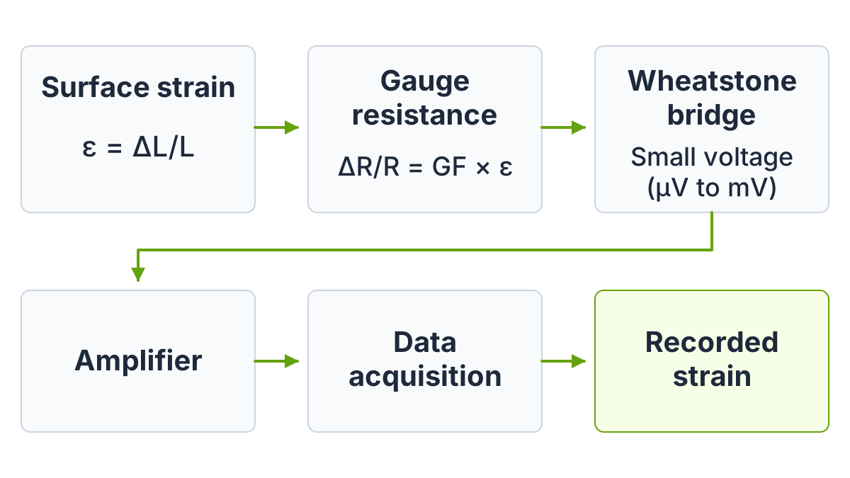
A bridge has four arms. When the resistance ratios on both sides match, the output is zero; when a gauge in one arm changes resistance, the output moves away from zero in proportion. Acromag’s whitepaper gives the scale: a 120 Ω gauge with a gauge factor of 2.00 at 3,000 µε changes by 0.6%, only 0.72 Ω.
How the bridge output then reaches a controller or logger, as a raw signal or through a transmitter, is covered in the signal and interface table of our industrial IoT sensor guide.
Takeaway: Budget for excitation, a bridge, amplification and a logger along with the gauge itself.
Gauge factor: the one formula you need
The gauge factor links resistance change to strain: GF = (ΔR/R) ÷ ε. ASTM E251 calls it the strain gauge’s transfer function and notes that strain data can be no more accurate than the gauge factor used to compute them.
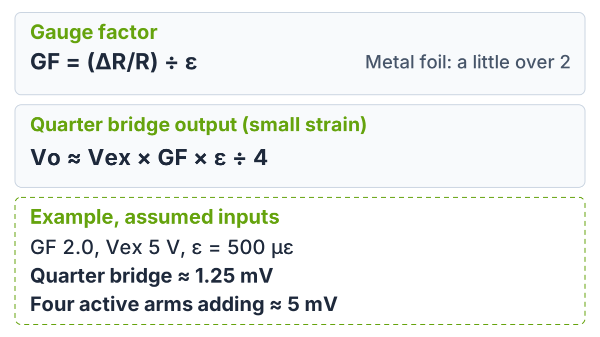
Worked example (example, assumed inputs): GF = 2.0, bridge excitation 5 V, strain 500 µε.
- Quarter bridge: Vo ≈ Vex × GF × ε ÷ 4 = 5 × 2.0 × 0.0005 ÷ 4 = 1.25 mV.
- Same strain with four active arms wired so their outputs add: about 5 mV.
The quarter-bridge formula is a small-strain approximation; the exact quarter-bridge output is slightly nonlinear in strain.
Common mistake: Entering 2.0 as the gauge factor for every gauge. Use the value stated for your gauge lot; a 2% difference in gauge factor is a 2% error in every strain value.
Takeaway: Copy the gauge factor from the gauge packaging into your instrument before the first reading.
Quarter, half or full bridge?
Use a quarter bridge for single-point stress analysis, add an unloaded compensating gauge when temperature changes, use a half or full bridge when two or four gauges can be placed so their strains add, as on a bending beam. Output rises with the number of active arms only when their strains add; the factors below assume equal, opposite-sign strains wired to add, at small strain.
| Configuration | Gauges | Relative output | Temperature compensation | Typical use |
|---|---|---|---|---|
| Quarter bridge | 1 active, 3 fixed resistors | 1× | Self-temperature-compensated gauge matched to the material | Stress analysis at many points |
| Quarter bridge with compensating gauge | 1 active, 1 unloaded “dummy” on the same material | 1× (the dummy adds no signal) | Dummy cancels thermal output if it sees the same temperature and has a matched response | Single point with changing temperature |
| Half bridge | 2 active (e.g. tension and compression faces) | 2× when strains are equal and opposite and wired to add | Partly self-compensating when both gauges see the same temperature | Bending beams |
| Full bridge (bending) | 4 active | 4× under the same conditions | Partly self-compensating; check residual thermal output | Load cells, pressure and torque transducers |
| Full bridge (axial, Poisson) | 4 active | 2 + 2ν | As above | Axial members |
Naming varies: Acromag’s whitepaper calls the one-active-plus-dummy arrangement a “Quarter-Bridge Type II”, while the Penn State lab describes it as a half bridge. This article uses Acromag’s naming.
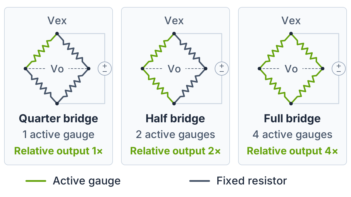
The dummy-gauge idea works because both gauges see the same temperature but only one sees load; it adds no mechanical signal, so it compensates without increasing output.
Takeaway: Choose the bridge by how many gauges you can place usefully, not only by how much signal you want.
Which strain gauge types and rosettes exist?
Two separate choices define a gauge: the sensing element and the grid layout. They combine, so a metal foil gauge can be a single grid or a rosette.
Sensing element:
| Element | What it is | Strength | Limitation |
|---|---|---|---|
| Metal foil | Etched foil grid on a thin backing | General purpose, GF a little over 2 | Small output; needs a bridge and compensation |
| Metal wire | Fine wire grid (Acromag lists foil or wire grids) | Simple construction | Foil is the common modern form |
| Semiconductor (piezoresistive) | Silicon element | Larger gauge factor, used for small strains (Wikipedia) | More expensive, more temperature-sensitive, fragile (Wikipedia) |
Grid layout:
| Layout | Grids | Use when | Limitation |
|---|---|---|---|
| Single grid | 1 | Strain direction is known | One direction only |
| Tee rosette | 2, perpendicular | Principal directions are known | Wrong if directions are unknown |
| 45° rectangular rosette | 3, at 0°, 45°, 90° | Principal directions are unknown | More channels and data reduction |
| 60° delta rosette | 3, at 0°, 60°, 120° | Principal directions are unknown | Same as rectangular |
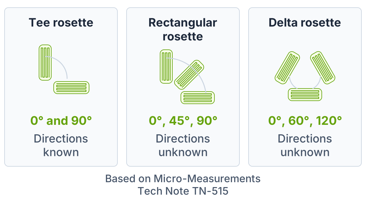
Micro-Measurements’ Tech Note TN-515 states the rule plainly: with the principal directions unknown, three independent strain measurements are needed, so use a rectangular or delta rosette; a tee rosette fits only when the directions are known in advance, as in a pressurized cylinder or a shaft in torsion. It also notes that rosettes come in planar and stacked constructions.
Takeaway: If you do not know the principal stress directions, use a three-grid rosette.
What causes strain gauge errors?
Temperature, transverse sensitivity, lead wires and installation are the main error sources to plan for; which dominates depends on the job. ASTM E251 calls thermal output an additive error that can be much larger than the strain from loading, and says it has to be determined on the same material as the test part, under representative temperature conditions.
| Error source | What happens | How it is handled |
|---|---|---|
| Thermal output | Resistance changes with temperature, not load | Self-temperature-compensated gauges matched to the material; dummy gauge or full bridge |
| Gauge factor temperature coefficient | Sensitivity drifts slightly with temperature | Usually small; correct for wide temperature swings |
| Transverse sensitivity | The grid responds a little to strain across its axis | Usually well under 10% of GF; correct when known |
| Lead wires | Wire resistance adds to the bridge arms | Lead-wire compensation in the wiring scheme or the instrument |
| Installation | Poor bonding transfers strain badly | Surface preparation and suitable adhesive |
Common mistake: Zeroing a quarter-bridge gauge at room temperature, heating the part and reading the change as load strain. The reading now mixes real thermal strain in the part with the gauge’s apparent thermal output, and room-temperature zeroing cannot separate them.
Acromag’s whitepaper adds that gauge makers match gauge materials to particular test materials to reduce temperature sensitivity, but additional compensation is usually still needed.
Takeaway: Plan temperature compensation before you bond the first gauge.
A 6-point strain gauge selection checklist
Six choices settle most first selections. Write them down before ordering:
- Test material. Pick self-temperature compensation matched to it.
- Gauge length. Match it to how quickly strain changes across the area of interest; the gauge maker’s selection guide gives the ranges.
- Pattern. Single grid when the strain direction is known; tee rosette when principal directions are known; rectangular or delta rosette when they are unknown.
- Resistance. 120, 350 or 1000 Ω, matched to the instrument’s bridge completion and excitation.
- Bridge configuration. Quarter, half or full, based on how many useful gauge positions you have.
- Environment. Temperature range, moisture and protective coating; installed gauges usually cannot be moved later.
If your instrument also has to publish data to a plant network, check its input type against our industrial IoT sensor guide before ordering.
Takeaway: Complete the checklist on paper; it doubles as the record of how each gauge was chosen.
Where are strain gauges used?
Engineers bond gauges directly to parts for experimental stress analysis, and manufacturers build them into load cells, pressure transducers and torque sensors. OIML R 60, the international recommendation for load cells, defines the strain gauge as the resistive element attached to a load cell structure, and piezoresistive pressure sensors use bonded or formed strain gauges on a sensing element (Wikipedia, “Pressure measurement”).
| Use | Where the gauge sits | Read more |
|---|---|---|
| Stress analysis | On the part under test | This page |
| Force and weight | Inside a load cell | Strain gauge vs load cell |
| Pressure | On a diaphragm inside a transducer | Sensor comparison table |
| Dimension, without contact | Not a strain gauge job | Optical gauge specs explained |
More sensor explainers are collected under sensors and DAQ, with instrument specifications under test and measurement and machine integration under automation.
Takeaway: If you need force, weight or pressure rather than surface strain, start from a packaged transducer.
When does this not apply?
This page covers bonded metallic and semiconductor resistance gauges and the small-strain bridge approximation; it does not apply to:
- Strains beyond the range the gauge maker specifies; the small-strain bridge formula also loses accuracy as strain grows.
- Very fast dynamic or impact events; check the bandwidth of the whole measurement chain first.
- Non-contact measurement; optical and video methods replace bonded gauges there.
- Results that must be traceable force or weight values; a calibrated load cell is the usual route.
Takeaway: Confirm your strain range, frequency and material suit bonded gauges before applying these formulas.
Related reading
Use these next, depending on the job:
- Strain gauge vs load cell — Decide whether a packaged transducer fits better than bare gauges.
- Industrial IoT sensors — Plan how bridge signals reach your control system.
- profileGAUGE C.ODC specs — See resolution, repeatability and linearity separated on a real datasheet.
Takeaway: Move to the comparison guide once you know you need force rather than strain.
Method and update log
Compiled on 7 October 2026 from the scope of ASTM E251, OIML R 60-1:2021, Micro-Measurements Tech Note TN-515 and technical article on full bridges, an Acromag whitepaper, Penn State and UTRGV teaching material, and encyclopedia articles marked where used. The worked example uses assumed inputs. Last reviewed 7 October 2026.
Takeaway: Check a figure against the source named next to it before reusing it in your own calculations.