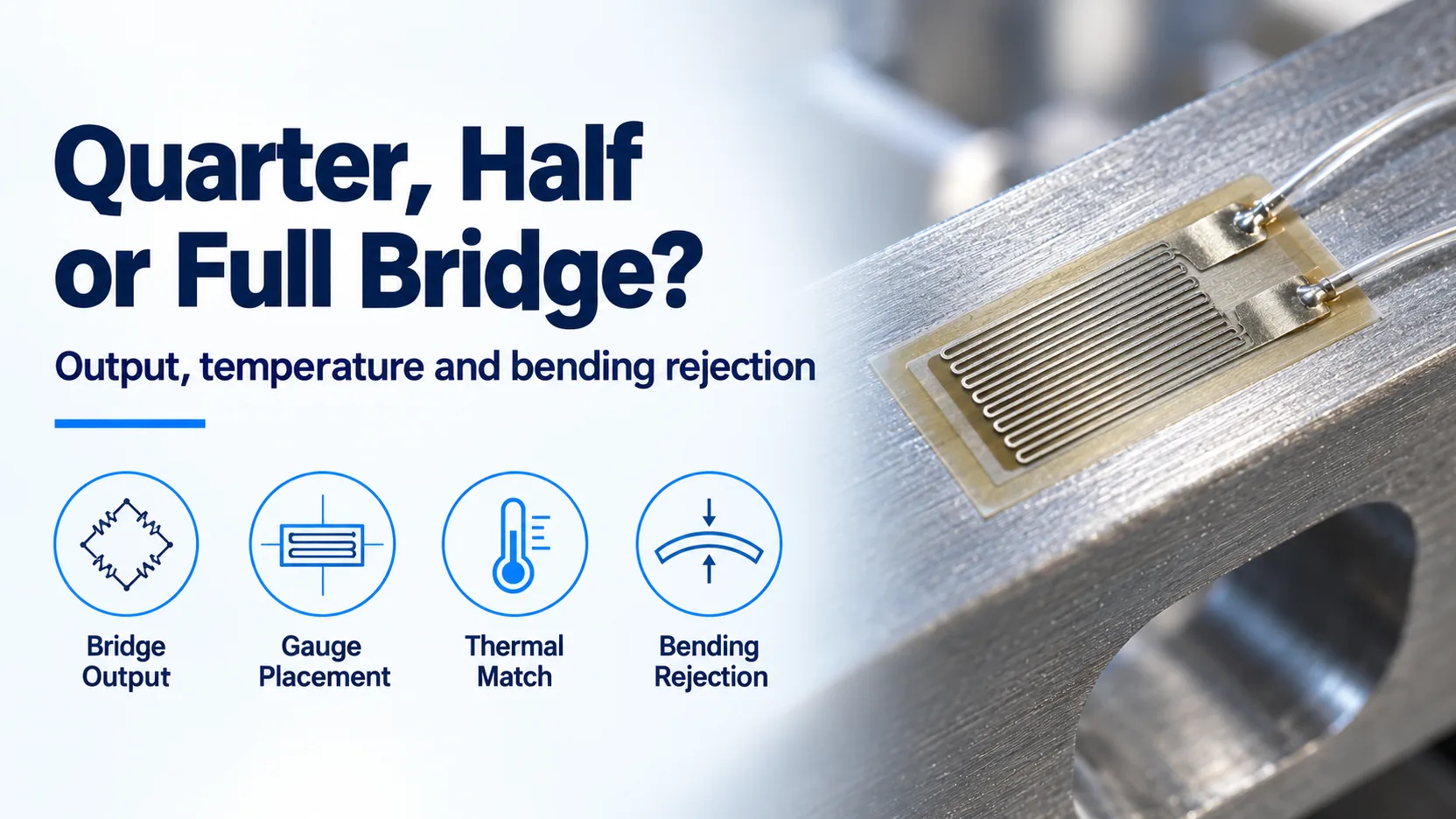
Choosing a strain gauge Wheatstone bridge by quarter, half or full designation alone can suppress the strain you wanted to measure. Relative output and cancellation depend on where each gauge sits and which electrical arm it occupies: a bending bridge rejects axial strain, while a correctly arranged axial full bridge rejects bending.
Choose the mechanical measurement first, then the bridge. Equal tension and compression strains can make a bending half bridge twice as sensitive as a quarter bridge, and a bending full bridge four times as sensitive. Those factors do not apply to every half or full bridge. Temperature cancellation also requires matched thermal responses; adding gauges does not remove a temperature gradient.
This comparison extends the strain gauge basics guide. It uses the configurations in NI’s SCXI-1520 User Manual (May 2009, Chapter 4) and Micro-Measurements’ bridge-output note (10 March 2023), retrieved on 19 October 2026. It addresses electrical and mechanical arrangement rather than product selection. More measurement guides are in Sensors and DAQ.
Which quarter, half and full arrangements add signal?
The familiar relative outputs apply to matched gauges, initially balanced arms and small strain, with the signs wired to add. The table uses quarter-bridge sensitivity as the reference. ν is the specimen’s dimensionless Poisson ratio; Poisson arrangements assume uniaxial stress at the gauge locations.
| Arrangement | Useful mechanical response | Relative output magnitude, small strain | Temperature or unwanted-load cancellation | Dominant failure mode and prevention |
|---|---|---|---|---|
| Quarter bridge, active gauge plus fixed completion | Local axial plus bending strain | 1× | No paired on-part thermal cancellation | Thermal output appears as load; match gauge compensation to the material and assess temperature effects |
| Active gauge plus unloaded dummy, NI quarter-bridge Type II | Local axial plus bending strain | 1×; dummy adds no load signal | Matched thermal output cancels when the dummy tracks the active gauge’s temperature on the same material | Dummy is strained or at a different temperature; keep it mechanically unloaded and thermally representative |
| Half bridge, longitudinal and transverse Poisson gauges | Local axial or bending strain | (1 + ν)× | Matched thermal effects cancel; bending remains in a surface measurement | Treating the transverse grid as unloaded; use the Poisson scaling and verify the stress state |
| Bending half bridge, longitudinal gauges on opposite faces | Bending strain | 2× | Rejects equal axial strain; matched thermal effects cancel | Unequal face strains or a thermal gradient; place gauges symmetrically and assess the gradient |
| Bending full bridge, four longitudinal gauges | Bending strain | 4× | Rejects equal axial strain; matched thermal effects cancel | Equal-sign strains wired into canceling arms; record the tensile and compressive arm assignments |
| Axial full bridge, longitudinal and transverse pairs on opposite faces | Axial strain | (2 + 2ν)× | Rejects symmetric bending; matched thermal effects cancel | Unsymmetrical placement or incorrect ν; verify opposite-face pairing and the material input |
Configuration definitions and cancellation behavior: NI, May 2009, manual pages 4-4 through 4-18. Relative factors are the small-strain limits of its conversion equations; the full-bending and full-axial factors are also stated by Micro-Measurements, 10 March 2023. All were checked on 19 October 2026. The table selects representative layouts; it is not a list of every possible full-bridge circuit.
Naming is not sufficient for setup: an active-plus-dummy pair can contain two bonded resistors yet still have only one load-sensitive arm. Record each grid’s location, orientation and electrical arm alongside the software’s bridge-type setting.
What bridge output ratio is actually measured?
Measure the differential output relative to excitation, with an unstrained baseline subtracted. NI defines the following ratio on manual page 4-3:
Vr = [VCH(strained) − VCH(unstrained)] / VEXHere VCH and VEX are voltages in volts; Vr is dimensionless, conventionally reported in mV/V. For this expression, excitation must remain constant between the baseline and loaded readings. If excitation varies, normalize each reading by its contemporaneous excitation before subtraction.

With the arm labels shown, voltage-divider algebra gives the ideal instantaneous ratio:
VCH / VEX = R3 / (R4 + R3) − R2 / (R1 + R2)This derived expression assumes negligible input loading and neglects lead resistance. The nominal bridge is balanced when the arm ratios match. For initially equal arms, an active tensile gauge in R4 produces a negative output with this polarity. Reversing the output leads reverses the sign; the sensitivity magnitudes below stay the same.
NI’s quarter-bridge conversion on page 4-5 is:
ε = −4Vr / [GF × (1 + 2Vr)] × (1 + RL/Rg)GF is the dimensionless gauge factor; Rg and RL are gauge and lead resistance in ohms, using the manual’s lead-resistance definition. Setting RL to zero for the ideal circuit and rearranging gives:
Vr = −GF × ε / (4 + 2GF × ε)
Vr ≈ −GF × ε / 4       when |GF × ε| is small
Use strain as a dimensionless fraction in these equations. This is the quarter-bridge ratio, including its nonlinearity, rather than a universal equation for every bridge arrangement.
Which arrangement cancels bending, and which measures it?
An opposite-face longitudinal pair can reject axial strain while retaining bending, because bending changes sign between the faces. An axial full bridge uses opposite-face longitudinal and transverse pairs to retain the common axial contribution while canceling symmetric bending.

For the bending half bridge, let the top and bottom longitudinal strains be εa + εb and εa − εb. Their difference is 2εb: the common axial term disappears. In the axial full bridge, the opposite-face longitudinal contributions sum to 2εa; the corresponding transverse contributions follow the Poisson response. These are algebraic consequences of the placements described in NI’s May 2009 manual, pages 4-11 through 4-18.
Equal thermal responses cancel through the same bridge symmetry. A dummy at a different temperature, different bonding conditions, or a through-thickness temperature gradient breaks that symmetry. Electrical thermal cancellation also does not separate a real mechanical strain caused by constrained thermal expansion from a load-induced strain.
Threshold rule: If accessible instrumented faces are fewer than two under a requirement to reject bending in an axial measurement, do not select the opposite-face axial full-bridge layout. Choose a quarter bridge to record local surface strain and resolve bending separately, because the required opposite-face cancellation is unavailable. The two-face requirement comes from NI’s full-bridge Type III arrangement, May 2009, pages 4-16 through 4-18; a single surface channel cannot supply that separation by itself.
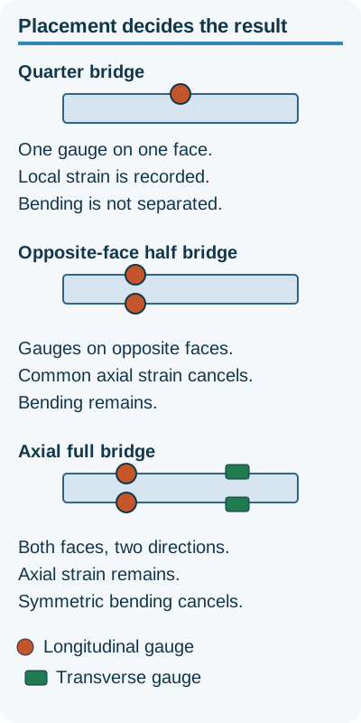
More gauges can add signal. Placement still decides whether bending is rejected.
Worked example: how much ratio does each bridge produce?
Assumed inputs for this calculation, 19 October 2026: GF = 2.0, tensile strain ε = +1,000 µε = 0.001, initially equal bridge arms, negligible lead resistance, and no temperature change. For bending layouts, the compressive grids experience −1,000 µε. These are calculation conditions, not measured results. The GF and strain values match the scale discussed in Micro-Measurements’ 10 March 2023 note.
Exact quarter Vr = −(2.0 × 0.001) / (4 + 2 × 2.0 × 0.001)
                 = −0.0004995005 V/V = −0.4995 mV/V

Small-strain quarter magnitude = 0.500 mV/V
Bending half magnitude        = 2 × 0.500 = 1.000 mV/V
Bending full magnitude        = 4 × 0.500 = 2.000 mV/V
The ideal matched equal-and-opposite bending layouts are linear in this model; their output polarity follows the arm assignments. A Poisson full bridge needs ν as well, so it cannot be assigned the bending full bridge’s multiplier. For an actual channel, apply the appropriate conversion equation and lead correction rather than copying the quarter-bridge expression.
What hidden costs follow the bridge choice?
Budget for access, bonding, cable routing and interpretation as well as gauge count. An opposite-face bridge can require fixture removal to reach the rear surface, and a damaged bond can force a repeat installation and zero check. A dummy gauge adds installation work without increasing mechanical sensitivity.
Long cables also introduce lead resistance that can reduce sensitivity even when their thermal drift cancels. Use the three-wire quarter-bridge checks for lead matching, terminal mapping and shunt calibration rather than repeating that procedure here. If the eventual measurand is force, include calibration and elastic-element design in the comparison with a finished load cell.
Method and sources
Updated 19 October 2026. Equations and mechanical rejection conditions were checked against the saved SCXI-1520 User Manual, revision 372583E-01, May 2009, Chapter 4, especially pages 4-3, 4-5, 4-10, 4-12 and 4-18. The sensitivity comparison was cross-checked against Micro-Measurements’ full Wheatstone bridge note, 10 March 2023. The voltage-divider rearrangement and worked arithmetic are derived here from those equations. No hardware specifications or product performance claims are inferred. This is an independent publication, unaffiliated with NI or Emerson.