Zeroing a quarter-bridge channel in software can hide a leadwire asymmetry or a misplaced shunt resistor until the cable warms up, building a temperature-drift error and sensitivity loss into every reading. The zero looks clean on the bench, while thermal drift and leadwire desensitization sit unrecorded in the run.
Copy the nominal gauge resistance, gauge factor, leadwire loop resistance, and terminal names from the foil package and the conditioner manual into the channel column below. The published-example column repeats only figures stated in Micro-Measurements Tech Tip TT-612, Tech Note TN-514, and National Instruments’ sensor white paper. Compiled from public sources by an independent publication (about this site). This site is not affiliated with National Instruments (NI) or Emerson.
Before balancing or scaling a three-wire quarter-bridge strain gauge channel, verify that two matched leadwires (R_L1 = R_L2) join at one gauge solder tab while the third conductor connects to the opposite tab, map the instrument end by electrical function rather than wire color, and check whether your shunt resistor lands across the completion arm rather than the sense-to-excitation terminals. In Micro-Measurements Tech Tip TT-612 (revised 16 August 2010), switching a 120 Ω quarter bridge with 20 ft (6 m) of 26 AWG copper cable from two wires to three wires cancels the 156 µε per 10 °F (5.5 °C) leadwire temperature drift and cuts the 7,000 µε initial bridge imbalance in half, while one leadwire (R_L) remains in series with the active gauge and retains half of the two-wire desensitization.
| Check item | Where to read or measure it | Your channel | Published reference case |
|---|---|---|---|
| Nominal gauge resistance (R_G) | Foil package engineering data sheet | 120 Ω, 350 Ω, or 1000 Ω (Micro-Measurements TN-514, Table 1) | |
| Gauge factor (F_G or GF) | Foil package lot sheet | 2.000 in TN-514 Table 1; ≈ 2.0 in TT-612 and NI white paper | |
| Completion resistor (R_4) | Conditioner manual or external bridge module | Matches nominal R_G in the adjacent bridge arm (TT-612, Figure 2) | |
| Leadwire pair resistance (R_L1, R_L2) | Two-wire loop measurement or AWG length table | 1.7 Ω total loop on 20 ft of 26 AWG copper (TT-612); 1 Ω per 15 m lead (NI white paper, p. 11) | |
| Sense lead (R_L3) | Bridge output / high-impedance sense terminal | Carries negligible current into a high-input-impedance voltage meter (TT-612) | |
| Unstrained offset / balance method | Software tare, bridge potentiometer, or buffered output null | Three offset-nulling methods compared in NI white paper, p. 13 | |
| Shunt resistor (R_C) and target ε_s | Shunt resistor label and TN-514 Eq. 7 | 59,880 Ω across a 120 Ω dummy arm for 1,000 µε at F_G = 2.000 (TN-514, Table 1) | |
| Conditioner terminal pins | Your DAQ or bridge module pinout table | Blank until copied from the module manual |
Takeaway: Fill the channel column only from the gauge package, measured lead resistance, and module pinout; leave any unverified cell blank.
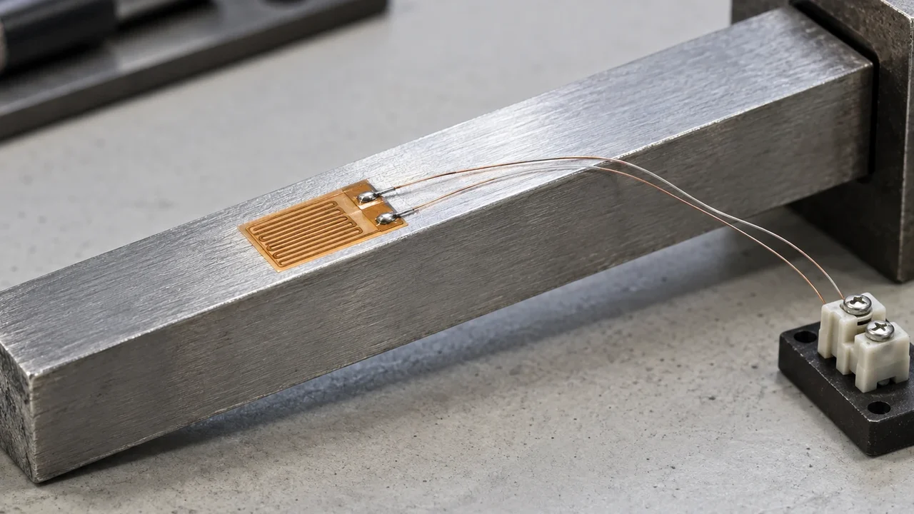
Why does a two-wire quarter bridge drift and lose sensitivity?
In a two-wire quarter-bridge circuit, both leadwires (R_L1 and R_L2) sit inside the active bridge arm in series with the strain gauge (R_G). Both Micro-Measurements Tech Tip TT-612 (revised 16 August 2010) and National Instruments’ Sensor Terminology and Architectures white paper (page 11) write the total resistance of that active arm as:
R_arm (2-wire) = R_G + R_L1 + R_L2
When the two conductors have equal resistance (R_L1 = R_L2 = R_L), the active arm sees R_G + 2R_L while the adjacent completion resistor (R_4) sits inside the instrument at nominal resistance R_G. That series resistance introduces three distinct errors stated in TT-612 and the NI white paper:
- Initial bridge imbalance: Before any mechanical load is applied, the extra resistance R_L1 + R_L2 unbalances the active arm relative to the completion arm. In TT-612’s worked example—20 ft (6 m) of 2-conductor 26 AWG (0.4 mm diameter) copper wire connected to a 120 Ω strain gauge with gauge factor 2.0—the room-temperature loop resistance is about 1.7 Ω, producing an initial bridge imbalance of approximately 7,000 µε.
- Leadwire temperature drift: Copper wire has a thermal coefficient of resistance that is roughly two orders of magnitude greater than that of a strain gauge alloy (NI white paper, page 11). TT-612 notes that copper resistance changes by about 22% per 100 °F (55 °C). In the same 20 ft, 26 AWG copper example on a 120 Ω gauge, a 10 °F (5.5 °C) change in cable temperature shifts the bridge output by 156 µε, which corresponds to an apparent stress error of 4,700 psi (0.03 GPa) in steel.
- Leadwire desensitization (span attenuation): Strain is only developed in the foil grid R_G, not in the copper leads, so the fractional resistance change across the entire arm is reduced by the ratio of leadwire resistance to gauge resistance. In TT-612’s 20 ft, 26 AWG two-wire example on a 120 Ω gauge, the two leads cause a sensitivity loss of about 1.5%. In NI’s example (page 11), two 15 m leads at R_L = 1 Ω each add 2 Ω in series with a 120 Ω gauge.
If you need the foundational bridge equations and foil-grid layout before checking leadwire effects, see our strain gauge basics guide.
| Error mechanism | Two-wire quarter bridge (R_L1, R_L2 in active arm) | Three-wire quarter bridge (R_L1 in active arm, R_L2 in dummy arm) | TT-612 published case (120 Ω gauge, 20 ft of 26 AWG copper, R_loop ≈ 1.7 Ω) |
|---|---|---|---|
| Initial resistance offset | Proportional to R_L1 + R_L2 | Proportional to R_L1 − R_L2 (plus single-arm imbalance before balance) | ≈ 7,000 µε in 2-wire; cut in half in 3-wire |
| Leadwire thermal output (ΔT along cable) | Full thermal resistance change of R_L1 + R_L2 appears as apparent strain | Cancels when R_L1 = R_L2 and both leads see the same temperature | 156 µε per 10 °F (5.5 °C) in 2-wire; eliminated in matched 3-wire |
| Leadwire desensitization (gain loss) | Two leadwires (2R_L) attenuate active gauge sensitivity | Reduced by 50%; one leadwire (R_L) remains in series with R_G | ≈ 1.5% loss in 2-wire; halved in 3-wire with gain factor R_G / (R_G + R_L) |
| Specimen thermal output of the gauge itself | Not canceled | Not canceled (Keyence NR-ST04 bridge table) | Requires self-temperature-compensated gauge or dummy gauge on unstrained specimen |
Takeaway: A two-wire run puts the full loop resistance and its copper temperature coefficient into a single bridge arm; moving to three wires splits the two current-carrying leads into adjacent arms.
How does the third wire split lead resistance across adjacent arms?
Micro-Measurements Tech Tip TT-612 (Figure 2) and StrainBlog’s comparison note dated 9 November 2023 describe the three-wire quarter bridge as shifting the electrical bridge corner from the instrument terminal out to the strain gauge solder tab:
- Conductor 1 (R_L1): Runs from the bridge excitation terminal (P+) to the first solder tab of the active strain gauge (R_G). It stays in series with R_G, so the active arm resistance is R_G + R_L1.
- Conductor 2 (R_L2): Runs from the second solder tab of the strain gauge back to the internal or external completion (“dummy”) resistor (R_4). That places R_L2 in series with R_4, so the adjacent completion arm resistance is R_4 + R_L2.
- Conductor 3 (R_L3): Joins Conductor 2 right at the second solder tab of the strain gauge and runs to the high-impedance bridge output sense terminal (S−). Because the voltage-measuring amplifier has high input impedance, negligible current flows through R_L3, and its resistance does not load either bridge arm.
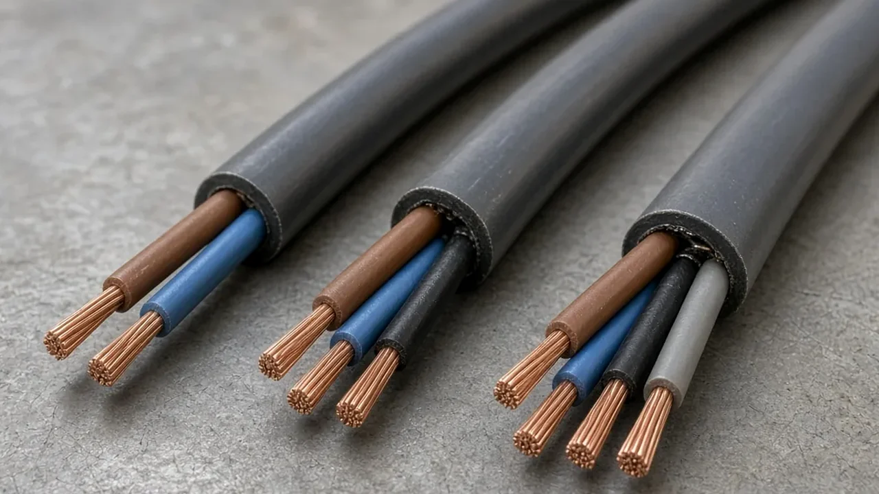
For the adjacent-arm resistance cancellation to hold in practice, TT-612 and Micro-Measurements’ note dated 9 November 2023 state three physical requirements for the current-carrying leads R_L1 and R_L2:
- Same conductor material and wire gauge (AWG): Both leads must have the same nominal resistance per unit length and the same temperature coefficient of resistance.
- Equal conductor length: Both leads must be cut to the same length so that R_L1 = R_L2 at room temperature.
- Same thermal environment along the cable route: Both leads must be bundled or jacketed together so they experience identical temperature changes from the specimen to the DAQ terminal block.
Even when R_L1 and R_L2 are matched, two effects remain that three-wire wiring does not cancel:
-
Single-lead desensitization: Conductor R_L1 is still in series with the active gauge R_G. Micro-Measurements Tech Note TN-514 (page 3) writes the resulting signal attenuation factor as:
Signal Attenuation Factor = R_G / (R_G + R_L)
Or, expressed as fractional sensitivity loss:
Fractional Loss = R_L / (R_G + R_L)
-
Gauge thermal output on the test part: Keyence’s strain gauge bridge comparison table explicitly separates Lead wire temperature compensation (marked
✓for the one-gauge, three-wire system) from Temperature compensation of the gauge on the test material (marked-for the one-gauge, three-wire system). If thermal expansion of the test piece must be rejected in the bridge itself, a two-gauge active-dummy bridge or a full-bridge transducer (see strain gauge vs load cell) is required.
Takeaway: Verify that the two bridge-arm conductors share the same wire gauge, cut length, and thermal path, and still account for the single-lead attenuation factor R_G / (R_G + R_L) when lead resistance is significant.
How do you map gauge tabs and DAQ terminals without guessing wire colors?
Micro-Measurements’ wiring tip dated 8 July 2015 (Wiring a Three-Wire Quarter-Bridge) states a rule that prevents backward-wiring confusion at the specimen: a foil strain gauge is not polarity-sensitive. At the gauge tabs, you can solder the single wire to the left tab and the joined pair to the right tab, or reverse them, and the electrical behavior of the gauge is identical.
Where mistakes happen is at the instrument end, when an operator wires by insulation color without checking which conductor is the single lead and which two conductors are joined at the gauge tab. Micro-Measurements’ pre-bonding guide dated 13 October 2015 illustrates a typical three-conductor ribbon lead (for example, 330-DFV or 326-DFV with red, white, and black insulation) where red is kept separate while white and black are twisted and tinned together so they share one solder tab. That color assignment is only a convention on that assembly—your cable and your conditioner terminal block can use different colors and pin labels.
| Conductor role | Connection at the strain gauge tabs | Connection at the conditioner / DAQ end | Continuity check before landing (cable disconnected from DAQ) | Your wire color / tag | Your DAQ pin label |
|---|---|---|---|---|---|
| Active-arm excitation lead (R_L1) | Soldered alone to Tab A | Bridge excitation terminal on the active gauge side (P+ in TN-514 Figure 4) | Reads nominal R_G + R_L1 + R_L2 to the joined pair; reads R_G + R_L1 + R_L3 to the sense wire | ||
| Completion-arm lead (R_L2) | Joined with R_L3 at Tab B | Internal or external completion (“dummy”) resistor terminal | Reads two-wire loop resistance R_L2 + R_L3 directly to the sense wire (R_L3) | ||
| Bridge-output sense lead (R_L3) | Joined with R_L2 at Tab B | High-impedance bridge output / sense terminal (S− in TN-514 Figure 4) | Reads R_L2 + R_L3 to the completion lead (R_L2) and R_G + R_L1 + R_L3 to the excitation lead (R_L1) |
Using an ohmmeter on the unpowered, disconnected three-wire cable lets you confirm both the conductor roles and the single-lead resistance R_L before landing the wires:
- Measure resistance between the two conductors joined at Tab B (R_L2 and R_L3). That reading is the round-trip leadwire loop resistance 2R_L (when all three conductors share the same gauge and length), so a single lead resistance is R_L = R_loop / 2.
- Measure resistance between the single conductor on Tab A (R_L1) and either of the Tab B conductors. That reading should equal R_G + 2R_L. Subtracting 2R_L confirms the installed gauge resistance R_G after bonding.
- Check resistance from any conductor to the metal test specimen. That insulation check sits outside the bridge loop and must remain open.
Common mistake: Swapping the single active-arm wire (R_L1) with one of the joined Tab B wires (R_L2 or R_L3) at the DAQ terminal block because the operator followed a color chart from a different cable assembly. If R_L1 and R_L3 are swapped at the conditioner, both current-carrying leads cease to sit in opposite arms and the circuit loses three-wire temperature compensation.
Takeaway: Identify the joined pair (R_L2, R_L3) and the single lead (R_L1) with an ohmmeter before connecting the terminal block, and record your module’s exact pin labels in the table.
How do bridge balance, offset nulling, and shunt calibration differ?
Balancing a bridge removes the unstrained zero offset; shunt calibration checks or scales the bridge span against a known parallel resistance. Treating a clean zero balance as proof of span calibration—or placing a shunt resistor across the wrong terminal pair—leaves gain errors undetected.
Bridge balance (offset nulling)
National Instruments’ Sensor Terminology and Architectures white paper (page 13) notes that a bridge is rarely at exact zero volts when unstrained because of small manufacturing tolerances in gauge resistance, completion resistor tolerance, bond-induced strain, and residual leadwire differences. NI compares three ways to handle that initial offset:
- Software compensation: You record the initial unstrained bridge output before loading and subtract it in software. NI notes this is fast and requires no manual trim, but it does not remove the electrical offset at the amplifier input—if the initial offset is large, it limits the amplifier gain you can apply and reduces dynamic range.
- Offset-nulling circuit (bridge balance potentiometer): A variable resistance network adjusts the bridge balance directly so the differential bridge output is zero under no-load conditions.
- Buffered offset nulling: An adjustable DC voltage is summed at the instrumentation amplifier output to null the offset after pre-amplification.
For single-ended vs differential grounding and common-mode bias return on non-bridge voltage channels, compare our floating DAQ input wiring sheet; if multiplexed channels show cross-channel carryover during high-impedance scans, run the DAQ ghosting test checklist.
Shunt calibration equation and standard resistor values
As explained in NI’s white paper (page 14) and Micro-Measurements Tech Note TN-514 (Shunt Calibration of Strain Gage Instrumentation, revised 30 August 2007, pages 1–3), shunt calibration connects a precision resistor R_C in parallel across one arm of the Wheatstone bridge to produce a known fractional resistance change ΔR / R that simulates a mechanical strain ε_s.
TN-514 (Equation 7, page 2) gives the shunt resistance R_C (in ohms) required to simulate a compressive strain of magnitude ε_s(µ) (in microstrain, 10^−6) across a gauge of resistance R_G and gauge factor F_G:
R_C = (R_G × 10^6) / (F_G × ε_s(µ)) − R_G
Solving for the simulated strain magnitude (in microstrain) when a known resistor R_C is shunted directly across an arm of resistance R_G gives:
ε_s(µ) = (R_G × 10^6) / [F_G × (R_G + R_C)]
TN-514 Table 1 (page 3) lists the exact shunt resistances calculated from Equation 7 for gauge factor F_G = 2.000 across 120 Ω, 350 Ω, and 1000 Ω bridge arms:
| Simulated strain ε_s(µ) at F_G = 2.000 | Shunt resistor R_C for R_G = 120 Ω | Shunt resistor R_C for R_G = 350 Ω | Shunt resistor R_C for R_G = 1000 Ω | Your R_C (Ω) |
|---|---|---|---|---|
| 500 µε | 119,880 Ω | 349,650 Ω | 999,000 Ω | |
| 1,000 µε | 59,880 Ω | 174,650 Ω | 499,000 Ω | |
| 2,000 µε | 29,880 Ω | 87,150 Ω | 249,000 Ω | |
| 5,000 µε | 11,880 Ω | 34,650 Ω | 99,000 Ω |
When the actual gauge factor F_G on the foil package differs from 2.000, TN-514 instructs scaling the simulated strain by 2.000 / F_G. TN-514 also notes (page 2) that quarter-bridge nonlinearity remains below 0.5% for simulated strains up to about 2,000 µε, so routine verification shunts stay in the small-strain region unless nonlinearity correction is part of the procedure.
Where the shunt resistor connects in a three-wire quarter bridge
In a three-wire quarter bridge with long leadwires, where you connect R_C changes what the shunt test actually measures. Micro-Measurements Tech Note TN-514 (Section III, Quarter-Bridge Circuit With Three-Wire Hookup, Figure 4, page 4) separates two goals and two shunt positions:
- Instrument verification vs instrument scaling (TN-514, pages 3–4):
- Instrument verification checks only whether the strain indicator or DAQ conditioner reads a known electrical unbalance correctly, excluding external leadwire losses.
- Instrument scaling calibrates the complete channel—including the single-lead attenuation factor R_G / (R_G + R_L)—by adjusting amplifier gain (or effective gauge factor) until the display matches the simulated strain ε_s with the leadwire effect included.
- Shunting the adjacent completion (“dummy”) arm for upscale / tensile simulation (TN-514, Figure 4):
- Because shunting a resistor lowers the resistance of the arm it parallels, shunting the active gauge simulates compressive (downscale) strain, whereas shunting the adjacent completion resistor R_4 at the instrument simulates tensile (upscale) strain.
- More importantly, TN-514 (page 4) demonstrates that in a three-wire hookup where the completion resistor equals the gauge resistance (R_D = R_G) and the two bridge-arm leads are equal (R_L1 = R_L2 = R_L), shunting R_C directly across the completion resistor inside or at the instrument automatically includes the leadwire attenuation factor R_G / (R_G + R_L) without requiring remote sense wires out to the gauge tabs.
- By contrast, TN-514 explicitly warns on page 4: “Gage strain cannot be accurately simulated by shunting from S− to P− (or from S− to P+).” Connecting R_C between the sense terminal (S−) and an excitation terminal places leadwire resistance inside the shunted loop and distorts the calibration signal.
Takeaway: Check your conditioner’s schematic to see which bridge arm its internal or external shunt switch parallels, and never jumper a calibration resistor blindly from the sense terminal to an excitation pin on a three-wire run.
Pre-measurement three-wire quarter-bridge verification sheet
Before starting a test run, copy the values from your gauge package, ohmmeter check, and DAQ channel setup into this verification table:
| Step | Verification check | Target / equation from cited sources | Your measured or configured value | Pass / hold |
|---|---|---|---|---|
| 1 | Foil package specs recorded | Copy nominal R_G and lot F_G from gauge package | ||
| 2 | Leadwire pair symmetry (R_L1, R_L2) | Same AWG, equal cut length, bundled in same thermal path (TT-612) | ||
| 3 | Round-trip loop resistance (2R_L) | Measure across the two Tab B leads (R_L2 + R_L3) at the disconnected cable end; R_L = R_loop / 2 | ||
| 4 | Active arm continuity (R_G + 2R_L) | Measure between single Tab A lead (R_L1) and Tab B lead; verify R_G = R_total − 2R_L | ||
| 5 | Terminal mapping by role | Land R_L1 on active excitation, R_L2 on completion arm, R_L3 on high-impedance sense (StrainBlog, 8 Jul 2015) | ||
| 6 | Unstrained bridge offset check | Record unstrained reading before software tare or hardware offset nulling (NI white paper, p. 13) | ||
| 7 | Leadwire attenuation factor | Calculate R_G / (R_G + R_L) (TN-514, p. 3); confirm whether software or shunt scaling compensates R_L | ||
| 8 | Shunt calibration check (ε_s) | Apply R_C across completion arm (TN-514 Fig. 4) or remote gauge tabs; compare reading to ε_s(µ) = (R_G × 10^6) / [F_G × (R_G + R_C)] |
Takeaway: Keep a channel on hold if the unpowered loop resistance 2R_L, the terminal role mapping, or the shunt arm location has not been verified against the module manual.
Where does this sheet stop?
This check sheet covers single-element foil strain gauges wired in a three-wire quarter bridge: leadwire resistance symmetry, terminal role mapping, offset nulling, and shunt calibration placement. Full-bridge transducer wiring and trade-offs between bonded gauges and factory-calibrated force sensors are covered in our strain gauge vs load cell comparison, while Wheatstone bridge fundamentals and rosette orientations are on the strain gauge basics page. For non-bridge voltage channels, see the floating DAQ input wiring guide and the DAQ ghosting test checklist. Additional measurement worksheets are available on the blog.
Method and sources
Compiled on 17 October 2026 from seven publicly accessible technical documents retrieved on 17 October 2026. Vishay Micro-Measurements Tech Tip TT-612 (The Three-Wire Quarter-Bridge Circuit, Document Number 11092, revised 16 August 2010) is used for the two-wire vs three-wire circuit equations, the three conditions for leadwire compensation, and the 20 ft (6 m), 26 AWG copper worked example on a 120 Ω gauge (1.7 Ω loop resistance, 7,000 µε imbalance, 1.5% sensitivity loss, and 156 µε per 10 °F thermal drift). Vishay Micro-Measurements Tech Note TN-514 (Shunt Calibration of Strain Gage Instrumentation, Document Number 11064, revised 30 August 2007) is used for the shunt resistance equation (Equation 7), the standard R_C values in Table 1, the signal attenuation factor R_G / (R_G + R_L), the distinction between instrument verification and instrument scaling, and the Section III / Figure 4 placement rules for three-wire quarter bridges (including the warning against shunting from S− to P− or P+). National Instruments’ white paper Sensor Terminology and Architectures (25188_Sensor_WhitePaper_IA.pdf, pages 11–14) is used for the 15 m, 1 Ω leadwire example, the copper-to-gauge temperature coefficient comparison, and the three offset-nulling methods. Micro-Measurements StrainBlog notes dated 8 July 2015, 13 October 2015, and 9 November 2023 are used for foil gauge tab non-polarity and pre-attached three-wire ribbon conventions. Keyence’s Measuring Strain With Strain Gauges reference page is used for the bridge comparison table distinguishing leadwire temperature compensation from specimen temperature compensation. Channel-specific cells remain blank until filled from the user’s hardware documentation. This site is an independent publication and is not affiliated with National Instruments (NI), Emerson, Vishay Precision Group, or Keyence.