A mismatched wire count or the wrong input type wastes the loop. You can still see 4 mA, the live zero, while the shunt ohms or the supply voltage on the sheet are still blank.
Fill the job column from the transmitter sheet and the DAQ manual. The example column repeats one pressure-loop case from National Instruments’ current-loop note updated 3 February 2025. Compiled from public sources by an independent publication (about this site). This site is not affiliated with National Instruments (NI) or Emerson.
Copy the transmitter wire count and the DAQ input type before you choose a resistor or a supply. NI’s current guide, updated 7 October 2024, says the NI 9203 measures current through an internal precision resistor and does not use an external shunt, while a general-purpose module such as the NI 9205 can measure current with an external shunt. The maximum expected current times that resistance has to stay inside the input range. Ohms, supply voltage, and loop resistance for your job stay blank until the manual states them. The 249 ohm resistor and the 24 V supply appear only in NI’s pressure-transmitter example.
| Field | What you copy | Your job | NI example, note updated 3 February 2025 |
|---|---|---|---|
| Wire count | 2, 3, or 4, as the transmitter sheet names it | ||
| Power path | Loop-powered, or a separate supply pair | DC supply, transducer, DAQ, and wires in series | |
| DAQ input | Current input, or voltage input | Precision shunt between the amplifier leads | |
| Shunt resistance | Ohms from the manual or the installed part | 249 ohm, which NI calls typical in that example | |
| Supply voltage | From the transmitter sheet and the supply you will use | ||
| Loop resistance | Ohms only if a manual you opened states them | ||
| Scale at 4 mA and at 20 mA | Engineering units from the calibration sheet | 4 mA is 0 percent, 20 mA is 100 percent |
Takeaway: Write the manual’s words into the job column, and leave a cell empty when that manual is silent.
Which wire count does the transmitter use?
The Transmitter Shop’s guide dated 30 July 2025 separates three arrangements.
A 2-wire transmitter uses two conductors for power and for the signal. It sits in the loop as a variable load and draws its operating power from the 4–20 mA current. The Transmitter Shop says 4 mA is the low end of the measurement and 20 mA is the high end.
A 3-wire transmitter uses two conductors for its own supply and a third for the signal. The same guide’s example of that supply pair is +24 V DC and a common, and it says the signal is referenced to that supply common. The +24 V figure is their example of the labels. Your supply cell stays blank until your sheet states the volts.
A 4-wire transmitter uses two conductors for power, which that guide says can be AC or DC, and two separate conductors for the signal. The guide describes that split as full separation of power and signal.
| Arrangement | Conductors, as The Transmitter Shop describes them | Power path | Your supply | Your terminal names |
|---|---|---|---|---|
| 2-wire | Two conductors carry power and signal | Drawn from the loop | ||
| 3-wire | Two for power, one for the signal | Separate supply; their example labels are +24 V DC and common | ||
| 4-wire | Two for power, two for the signal | Separate supply, AC or DC on that page |
NI’s current-loop note, updated 3 February 2025, adds two further names. Type 3, in that note, is two transducers in one package, installed in the same way as the 2-wire transmitters the note has already described. Type 4 uses separate connections for power and for the current measurement. NI says that split lifts the isolation requirement at the measuring device, and that the power pair still has to run the cable distance, so many applications place the supply near the transducers.
The pages opened here do not define the words active and passive. If your manual prints one of those words, copy it beside the wire count. The wiring follows the wire count and the power path on that manual.
The Transmitter Shop says a standard 4–20 mA loop joins one transmitter to one receiving device. NI’s note adds further transducers in parallel on the supply, so that supply voltage does not have to change, and in the 24 V example the new transducer’s maximum operating voltage must not be lower than that 24 V. An extra meter goes in series on the loop you already have, and NI says you then recalculate the voltage.
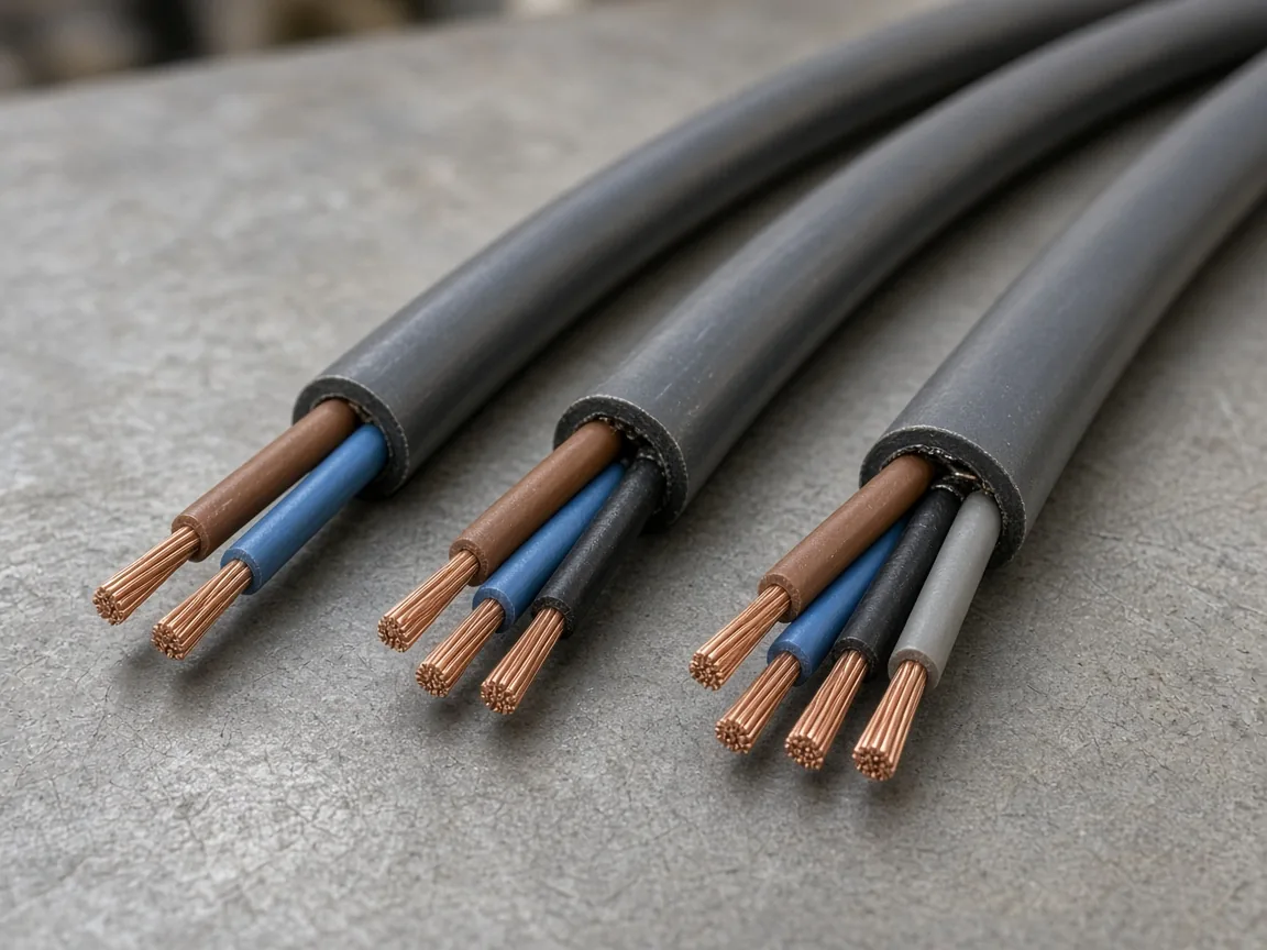
Takeaway: Count the conductors on the transmitter sheet, and leave the supply cell blank until that sheet states the volts.
Does the DAQ measure current, or the voltage on a shunt?
NI’s current guide, updated 7 October 2024, writes Ohm’s law as I = V/R, with current in amperes, voltage in volts, and resistance in ohms. The same guide says today’s meters are voltmeters with a precision resistor.
Two module examples are on that page. The NI 9203 has an internal precision resistor, so the guide says it does not need an external shunt. The NI 9205 is the guide’s example of a general-purpose input that measures current with an external shunt. Your module name and which of those two cases it is stay blank until your manual says so.
NI says a resistor is acceptable when the maximum expected current times the resistance stays inside the input range of the meter or the DAQ. A smaller resistance disturbs the circuit less and produces a smaller voltage, so the guide tells you to weigh resolution against that disturbance. If the external circuit shares a ground with the computer, the guide says to place the shunt close to the ground leg. Otherwise the common-mode voltage can sit outside the device rating.
Core Sensors’ wiring page, which shows no publication date in the archive, gives an order for a milliamp input on their 2-wire loop-powered sensors. Supply positive goes to the transducer +V. Transducer -V goes to the milliamp input. The meter or DAQ common returns to supply negative. A case-ground pin, when the sensor has one, is outside that loop on their page. The same page states three excitation lines: typically 8–32 V DC, a product-row figure of 10–28 V DC, and a listed need for at least 10 V DC. Those lines belong to that page. They do not fill your supply cell.
| Check | What the opened pages assign | Your entry |
|---|---|---|
| Current input with an internal resistor | NI 9203 example: no external shunt | |
| Voltage input used for current | NI 9205 example: external shunt; current times resistance inside the input range | |
| Shunt ohms | Manual, or the part you install | |
| Voltage at 20 mA | 0.020 A times the ohms you recorded | |
| Milliamp-input order | Core Sensors: supply + to +V, -V to the milliamp input, common back to supply − | |
| Your terminal names |
For the 249 ohm example only, 0.004 A times 249 ohm is 0.996 V, and 0.020 A times 249 ohm is 4.98 V. NI states that this resistor maps the loop to a range of 1 to 5 V. Your ohms cell is still blank, so your voltage cells stay blank.
Common mistake: Copying 249 ohm or 24 V from the example column onto a module whose manual states a different resistor or a different supply.
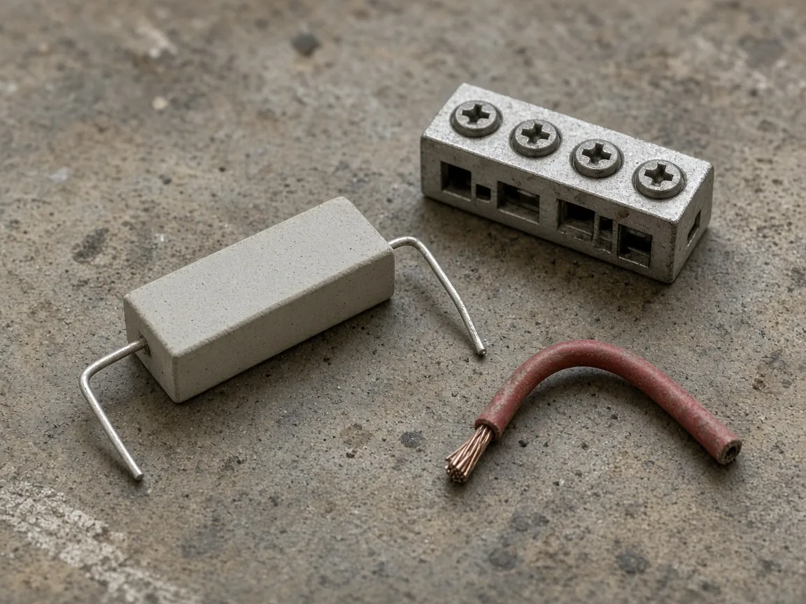
Takeaway: Record whether the input already contains a resistor. Multiply only after the ohms cell has a figure from the manual or the part.
What supply voltage does this loop require?
NI’s current-loop note lists the series parts as a DC supply, the transducer, the DAQ, and the wires. The transducer sets the current from 4 to 20 mA. NI says 4 mA is a live zero, 20 mA is the maximum signal, and 0 mA means a break in the loop. The current guide updated 7 October 2024 says that live zero lets the receiver tell a zero signal from a broken wire or a dead instrument. The Transmitter Shop says a 0 mA reading indicates a fault.
The voltage rows below use only figures those pages state. The job column stays empty.
| Drop | How you fill it | Your job | NI pressure example |
|---|---|---|---|
| Transmitter minimum | Transmitter sheet | 12 V | |
| Transmitter maximum | Transmitter sheet | 30 V | |
| Shunt drop at full scale | 0.020 A times the ohms you recorded | NI states a 1 to 5 V map for 249 ohm, and says adding that drop to the 12 V minimum suggests 17 V | |
| Wire drop | Length, gauge, and a resistance figure you have opened | 24 AWG solid copper at 2.62 ohm per 100 ft; 1.05 V on one 2,000 ft conductor; about 2.1 V for the pair | |
| Extra series meter | 0.020 A times that meter’s shunt | 105 ohm; NI states a maximum of 2.1 V and a total of about 21.2 V | |
| Supply you will use | Covers the drops you filled, and stays within the transmitter maximum | NI says 17 V leaves the transducer below its minimum once the wire drop is included, and 24 V meets that example | |
| Loop resistance |
The loop-resistance row is blank in both columns. The Transmitter Shop lists exceeding the allowable loop resistance as an installation mistake and does not print the ohms. NI prints 2.62 ohm per 100 ft for 24 AWG solid copper in the example, and the voltage drops above, and does not print a single loop-resistance limit.
On isolation, NI’s example puts both input pins on +14 V of common-mode voltage, with +2 V of normal-mode voltage, and calls the working voltage +16 V. The note says many DAQ devices have a maximum input range of ±10 V, and that an isolator has its own common-mode limit. Your common-mode limit stays blank.
Takeaway: Add only the drops you have filled. A blank ohms cell or a blank wire-drop cell means the supply cell stays blank too.
How do you scale the current to the process unit?
NI’s current guide says 4 mA represents 0 percent and 20 mA represents 100 percent. The Transmitter Shop says the transmitter moves the current in proportion from the minimum calibrated value at 4 mA to the maximum calibrated value at 20 mA. The span between those two stated endpoints is 16 mA.
When your calibration sheet uses that proportional map:
percent = (I in mA − 4) / 16 × 100
engineering units = low + (percent / 100) × (high − low)
Low and high stay blank until the calibration sheet states them. If you measured volts, I in amperes is V / R, and only after R is filled. At the NI example endpoints, 0.996 V / 249 ohm is 0.004 A, and 4.98 V / 249 ohm is 0.020 A, which are 4 mA and 20 mA. That check uses the example resistor. It does not fill your scale cells.
A constant 4 mA is the live zero. The Transmitter Shop’s troubleshooting table also lists a constant 4 mA as a possible sensor fault or a process sitting at the minimum of the range. A 0 mA reading is the break the NI note and the Transmitter Shop both describe.
Takeaway: Scale from 4 mA and 20 mA only after the calibration sheet gives the engineering units, and after the current itself comes from a filled resistor or a current input.
Where does this sheet stop?
The sheet covers wire count, the choice between a current input and a shunt on a voltage input, and the voltage drops you can actually fill. A floating voltage source on a differential input uses the bias-return and common-mode sheet. Terminal numbers, hazardous-area installation rules, and a survey of industrial networks sit outside it. Interface context for 4–20 mA beside other sensor outputs is on the industrial IoT sensors page. After the input is a current or a shunt voltage the module accepts, the sample-rate worksheet is the next budget. Other instrument notes are on the blog.
Method and sources
Compiled on 14 October 2026 from the four public pages listed at the end of this article. The text used here is the 11 October 2026 archive of those pages. The Transmitter Shop guide shows the date 30 July 2025 and is used for the 2-wire, 3-wire, and 4-wire split, for the one-transmitter loop, and for the troubleshooting lines on 0 mA and a constant 4 mA. Core Sensors’ wiring page shows no publication date in that archive and is used only for their milliamp-input order and for the three excitation lines quoted above. NI’s current-loop note shows an update date of 3 February 2025 and is used for the series parts, the 249 ohm example, the 12 to 30 V transducer, the wire figures, the 24 V conclusion, the extra 105 ohm meter, and the Type 3 and Type 4 descriptions. NI’s current guide shows an update date of 7 October 2024 and is used for Ohm’s law, the NI 9203 and NI 9205 examples, shunt placement, and the 4 mA / 20 mA percent statement. Example numbers stay in the example column. This site did not wire a loop and did not measure a device. National Instruments product names appear only where those public pages name them. Nothing here is an NI or Emerson document, and nothing here is investment advice.