The wrong cold-junction sensor location can leave a thermocouple channel drifting even when the measured object is steady. Cold junction temperature sensing must represent the thermocouple-to-copper transition temperature. Start by locating that transition and the sensing element used by your DAQ, then compare their behavior during ordinary warm-up.
The worksheets below help you record those locations and observations. They do not assign an accuracy limit or a settling time to an unidentified module. This is an independent technical publication, not an NI or Emerson site.
| Check first | Record from the unit or its manual | Why it matters |
|---|---|---|
| Transition location | Terminal, connector, or external junction block | Identifies the region the CJC measurement must represent |
| Selected CJC source | Built-in, external, or constant, if supported | Identifies the temperature actually used in conversion |
| Sensing element | Physical location and assigned channel or group | A software value alone does not locate the sensor |
| Operating state | Cover, airflow, orientation, powered equipment | Makes later observations comparable |
| Acceptance criterion | Model-specific specification and application requirement | No universal mismatch threshold is supplied here |
Locate the metal transitions before choosing a sensor position
TI’s SLOA204, page 3, identifies the reference junctions where thermocouple alloys meet the board’s copper conductors. Treating them as one reference requires equal temperatures. The word cold does not require refrigeration.
On your assembly drawing, trace each conductor to its material transition. Record intervening connectors and extension leads; do not assume the visible DAQ socket is the only transition. If the connector metallurgy is unknown, write Unknown / verify on the unit. A connector’s appearance cannot identify its alloy.
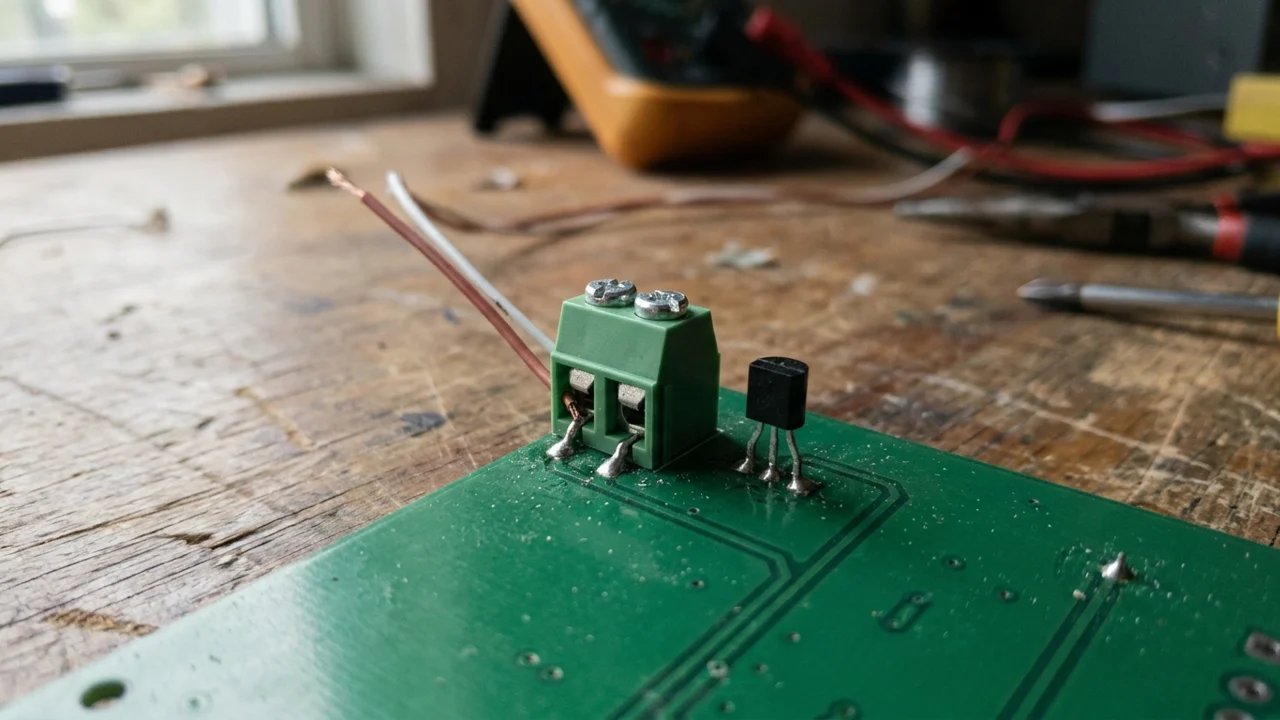
Copy this placement record into your commissioning notes. Use the manual’s terminal names rather than assigning new ones.
| Location to identify | Your assembly | Evidence to attach |
|---|---|---|
| Positive conductor’s transition to copper | Drawing detail or manual page | |
| Negative conductor’s transition to copper | Drawing detail or manual page | |
| Intervening connector or external junction block | Material specification and location | |
| CJC sensing element | Sensor location from module documentation | |
| CJC sensor assigned to this input | Configuration export or screenshot | |
| Nearby power components and airflow path | Photo with the operating arrangement recorded |
If the transition is in an external box, establish how that location is represented in the configured compensation before proceeding. NI’s historical SCC-TC guide gives a concrete warning: an SCC-TC02 used with an uncompensated panelette can suffer error from the temperature gradient between module and panelette junctions. That example explains the location problem; its terminal assignments do not apply to other modules.
Confirm what the DAQ uses for compensation
Find the input’s thermocouple type, selected CJC source, and any source-channel assignment in the device documentation and acquisition configuration. Copy the actual setting names. If the driver does not expose a separate CJC reading, record that limitation instead of inventing a value.
Analog Devices’ 2007 guide describes three architectures. A local sensor near the connector assumes both locations have approximately equal temperature. In its remote-diode example, the sensing transistor sits on the connector while the reading IC is elsewhere. Its integrated-converter example senses temperature inside the converter. The practical inference is that locating an IC does not always locate the temperature-sensitive element.
| Configuration question | Entry to retain | If you cannot establish it |
|---|---|---|
| Which CJC source is selected? | Exact option and source assignment | Resolve from the manual and saved task configuration |
| Where is its sensing element? | Connector, terminal assembly, or die location | Do not equate it with room temperature |
| Is a constant reference selected? | Value, units, and reason it represents the junction | Do not accept a room-air reading as justification |
| Is this a temperature task or raw-voltage acquisition? | Task type and conversion owner | Trace the software path before adding compensation |
| Which thermocouple type and units are configured? | Wire specification, input setting, output units | Resolve mismatches before judging placement |
For raw-voltage processing, use the device’s documented conversion sequence. The SCC-TC manual, pages 5–6, separates amplifier scaling, reference-temperature measurement, conversion of that reference to a thermocouple-equivalent voltage, voltage addition, and conversion back to temperature using the correct thermocouple type. Those steps explain why adding a CJC temperature directly to an arbitrary voltage is invalid. The historical module’s gains and channel numbers are not settings for your unit.
As an editorial check, identify one owner for compensation in your signal path: hardware, driver, or your conversion code. Establish what has already been applied before adding another correction.
Check the thermal environment in its operating arrangement
TI recommends locating the sensor close to the isothermal region, keeping the reference junctions away from heat sources, and reducing airflow around them. It also warns that board orientation can change heating from components below the junctions. Proximity alone therefore does not establish temperature agreement.
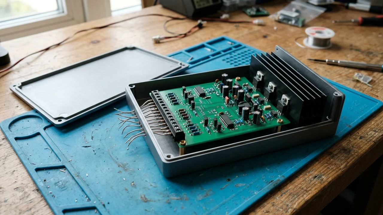
For an existing DAQ module, follow its installation instructions; a placement investigation is not a reason to relocate its built-in sensor. For a new board, compare the proposed layout with the manufacturer’s thermal guidance before accepting a sensor position. No fixed distance in millimeters proves that a location is suitable.
Our suggested observation sequence is:
- Save the configuration and record the enclosure, orientation, fan state, and neighboring powered equipment. Use the manufacturer’s required warm-up conditions when specified.
- Keep the measuring junction in a stable, documented reference condition. If that temperature is changing, you cannot attribute output movement to the terminal region alone.
- Use an appropriate independent contact reference at a documented, accessible location near the transition region, following the equipment’s access and isolation instructions. Record the reference instrument and its stated uncertainty. A plastic surface or nearby air measurement is a proxy, not a direct measurement of the buried junction.
- Log available CJC data, the local reference, and the thermocouple output through warm-up and after the readings settle under your documented criterion. Keep any manufacturer-required covers in their operating position. If opening a cover is required for access, record the changed condition and its limit on the comparison.
- Repeat in the normal operating arrangement after any permitted correction. Change one documented condition at a time so that the comparison remains interpretable.
Do not heat a terminal with a hand or heat gun and treat the result as calibration. This worksheet proposes an observation method; it supplies no measured results.
Record the readings before deciding what the drift means
Use the blank log below for each observation. Put units beside every temperature. Leave unavailable readings blank. Add timestamps for your actual observation interval rather than borrowing a warm-up duration from another model.
| Observation | Before settling | After settling | After permitted correction |
|---|---|---|---|
| Timestamp and elapsed time | |||
| Enclosure, airflow, orientation, load state | |||
| Measuring-junction reference condition | |||
| CJC value and units, if accessible | |||
| Independent local reference and units | |||
| Exact local-reference contact location | |||
| Reference instrument and uncertainty | |||
| Thermocouple output and units | |||
| Configuration version and source assignment |
For matching timestamps and units, you may record CJC reading minus local-reference reading as an observed difference. Keep that label: a surface probe’s contact quality, response, location, and uncertainty limit what the difference establishes. It is not automatically the DAQ’s CJC error, and it is not automatically the hot-junction error. An empty CJC field means this comparison cannot be calculated.
Set acceptance against the actual module’s conditions and the application’s measurement requirement. This log supports troubleshooting; it does not replace a documented calibration or uncertainty assessment.
Choose the next investigation from the observation
The branches below are editorial prompts for the next check, not diagnoses proven by correlation.
| What you observe | Next check | What the observation does not prove |
|---|---|---|
| Output movement follows changes near the terminal region while the measuring reference stays steady | Review transition location, sensor assignment, airflow and neighboring heat sources | Which component is wrong, or a numerical CJC error |
| Exposed CJC reading and local reference diverge during warm-up | Recheck sensor location, reference contact and time alignment | That either instrument is calibrated incorrectly |
| Local reference and CJC agree, but a steady offset remains | Check thermocouple type, units, polarity and conversion path | That thermal placement is correct in every operating state |
| Output becomes erratic or reaches an input limit | Follow the module’s open-input and electrical checks; review the floating-source bias and common-mode guide where applicable | That a thermal adjustment will fix an electrical fault |
| A connector, cable, or terminal assembly was replaced | Rebuild the transition map and verify the replacement’s specified materials | That visually similar connectors are interchangeable |
For broader interface choices, use the industrial sensor overview. Once the temperature path is understood, the DAQ sample-rate worksheet addresses acquisition timing. Neither replaces this terminal-location check.
Method and sources
Prepared on 15 October 2026 from primary documents fetched that day. TI SLOA204 (August 2014), page 3, supports the transition, isothermal-region and thermal-environment guidance. Analog Devices’ guide (26 April 2007), especially its application-circuit examples, supports the distinction between local, remote and integrated sensing. NI’s historical SCC-TC Series manual, pages 5–6, supports the conversion sequence and the limited uncompensated-panelette example.
These older documents explain physical principles and specific circuit examples; they do not establish current availability or the settings of an unidentified DAQ. The worksheets and troubleshooting branches are our editorial synthesis. No assembly was tested for this article. Model-specific warm-up time, tolerances, metallurgy, channel mapping and configuration remain items to verify on the unit.