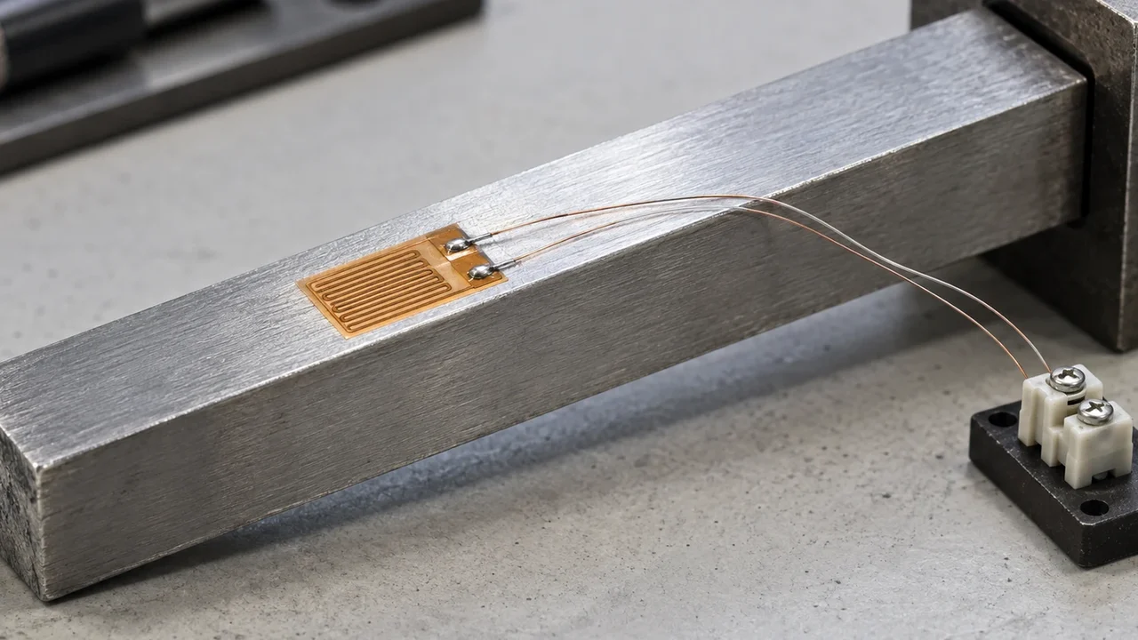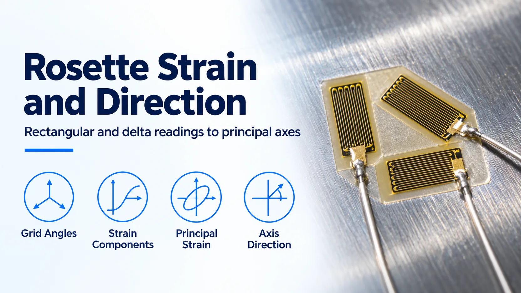
A swapped grid label can turn a strain gauge rosette’s principal strain orientation into the wrong physical direction. A rectangular rosette uses 0°/45°/90° grids and a delta rosette uses 0°/60°/120° grids; both recover the in-plane principal strains and their orientation when the readings represent the same local strain field.
Obtain the normal and engineering shear components from the correct rosette equations, then calculate the principal strains and use a quadrant-aware half-angle calculation for direction. The answer is measured from the reference grid, not automatically from a specimen edge. When the principal strains are equal, there is no unique principal direction.
The layout definitions, reduction equations and numbering cautions below follow Micro-Measurements’ TN-515, revised 14 August 2014, retrieved on 19 October 2026. This calculation guide extends strain gauge basics and belongs to Sensors and DAQ. It concerns local in-plane strain; obtaining stress additionally requires the appropriate material constitutive relationship.
Rectangular versus delta: what changes in the calculation?
The angular spacing changes the conversion to Cartesian components. It does not change the physical principal strains recovered from an ideal common strain field. Let x coincide with Grid 1, and number subsequent grid axes counterclockwise, viewed from the instrumented surface.

The following angular definitions and failure cautions are from TN-515, revision 14 August 2014, Sections 1–3, checked on 19 October 2026.
| Pattern | Grid axes relative to Grid 1 | Practical selection consideration | Dominant failure mode and prevention |
|---|---|---|---|
| Rectangular | 0°, 45°, 90° | Orthogonal outer grids make the component calculation easy to inspect | Interchanging the middle and outer grids corrupts magnitudes and direction; verify the grid map |
| Delta | 0°, 60°, 120° | Choose by installation space, tab arrangement and availability rather than assuming it measures a different strain quantity | Reversing the rotational sequence changes the direction result; document the viewing side and numbering |
| Tee | Two perpendicular axes | Suitable when principal directions are already established | Assuming unknown principal directions misses the shear component; use a three-grid rosette when directions are uncertain |
Planar versus stacked construction is a separate choice. Closely spaced planar grids still sample different surface locations. A stacked rosette brings their centers together, but its stiffness, heat dissipation and height above the surface can matter, particularly on compliant materials or thin parts in bending. A concentrated strain gradient cannot be fixed by choosing the right reduction formula.
How do the three readings become strain components?
Use ε1, ε2 and ε3 for the corrected normal strains reported by the individual grids, not raw bridge voltages. Match the grid ordering to the angular pattern before substituting readings. These Cartesian conversions assume small (infinitesimal) strain and a common local strain field across the grids. TN-515, Section 6, printed page 8, states the uniform-field assumption and explains that the Section 4 equations and Mohr’s circle use infinitesimal-strain theory. A finite-strain application needs a separate large-strain reduction checked against the accuracy the measurement requires. TN-515’s Appendix, pages 11–12, gives these conversions for counterclockwise numbering, with x along Grid 1:
Rectangular, 0°/45°/90°:
εx  = ε1
εy  = ε3
γxy = 2ε2 − ε1 − ε3

Delta, 0°/60°/120°:
εx  = ε1
εy  = [2(ε2 + ε3) − ε1] / 3
γxy = 2(ε2 − ε3) / √3
γxy is engineering shear strain. Its half, γxy/2, is the off-diagonal strain-tensor component. Keeping that distinction prevents a factor-of-two error in the principal-strain calculation. All strain terms may use µε consistently; convert to dimensionless strain if subsequent equations require it.
How is the principal strain direction obtained?
Find the maximum and minimum normal strains from the center and radius of the strain circle, and compute the maximum-strain direction from the same components. These principal-strain and direction equations likewise assume small (infinitesimal) strain and a common local strain field, consistent with TN-515, Section 6, printed page 8. The following is a component-form implementation of TN-515’s Appendix and Section 4 relationships:
C  = (εx + εy) / 2
R  = √[((εx − εy)/2)² + (γxy/2)²]
εP = C + R                 algebraically maximum principal strain
εQ = C − R                 algebraically minimum principal strain

φP = ½ atan2(γxy, εx − εy)
φQ = φP + 90°
atan2(y, x) here means the mathematical argument order: shear term first, normal-strain difference second. Check the function signature in the software used. Convert the returned angle from radians to degrees before reporting degrees. Positive φ is counterclockwise from Grid 1, viewed from the instrumented surface; principal axes are lines, so angles separated by 180° describe the same axis.
TN-515 warns that an ordinary inverse tangent of a quotient cannot by itself distinguish the two principal axes. The atan2 form implements that quadrant choice without dividing by a possibly zero normal-strain difference. It is a computational reformulation, not a different gauge calibration.
To report direction from a specimen datum, record the installed counterclockwise angle α from that datum to Grid 1, then use φP,datum = α + φP, interpreted as an axis modulo 180°. Keeping the reference frame in the result prevents an otherwise correct angle from being applied in the wrong direction.
Worked angle example with assumed gauge readings
Assumed rectangular-rosette readings, constructed for this example on 19 October 2026: ε1 = +800 µε at 0°, ε2 = +700 µε at 45°, and ε3 = +200 µε at 90°, numbered counterclockwise. Assume the grids sample the same uniform in-plane strain field and their channel corrections have already been applied. These readings are illustrative inputs, not test results.
εx = 800 µε; εy = 200 µε
γxy = 2 × 700 − 800 − 200 = 400 µε
C = (800 + 200) / 2 = 500 µε
R = √(300² + 200²) = 360.56 µε

εP = 500 + 360.56 = +860.56 µε
εQ = 500 − 360.56 = +139.44 µε
φP = ½ atan2(400, 600) = +16.85°
φQ = 106.85°
Thus the maximum principal strain points along an axis 16.85° counterclockwise from Grid 1. Both principal strains in this assumed case are tensile; “minimum” does not necessarily mean compressive. If Grid 1 is aligned with the specimen datum, this is also the datum-referenced direction.

As a substitution check, the directional normal-strain equation is:
ε(θ) = εx cos²θ + εy sin²θ + (γxy/2) sin(2θ)For the assumed example, θ = 45° gives ε = 400 + 100 + 200 = 700 µε, recovering the diagonal-grid input. This is an algebraic consistency check using the strain transformation behind TN-515, not an independent calibration. For a delta rosette, first use the delta component equations and then the same principal calculation; do not put delta readings into the rectangular equations.
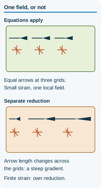
Scope of the reductions above. TN-515 Section 6, page 8. No universal strain cutoff.
When should the orientation be treated as unresolved?
Equal principal strains make every in-plane direction principal. TN-515 explicitly identifies the equal-reading case as indeterminate; a software library returning a number for atan2(0, 0) does not supply a physical direction.
Threshold rule: If the calculated principal-strain separation Δε = εP − εQ is less than its evaluated uncertainty UΔ, in µε, under the intended load and temperature conditions, choose to report the orientation as unresolved at that uncertainty level. Small errors can dominate the difference that sets direction. This is an engineering reporting rule derived from the equal-strain degeneracy, not a fixed accuracy specification from TN-515. Obtain UΔ from the installation’s uncertainty analysis rather than assuming a universal microstrain cutoff.
Also hold the direction result when the viewing side, rotational sequence or installed datum angle is unknown. Consistent apparent thermal strain added to every grid shifts the principal magnitudes without rotating the ideal axes; unequal thermal errors can rotate them. Large gradients between grids undermine the common-field assumption.
What hidden costs belong in a rosette installation plan?
Allow for separate conditioned measurements of the grids, lead identification, lot-specific corrections and documenting the datum angle. A missing channel or an unreadable grid map can require a repeat installation and loading sequence; an apparently inexpensive rosette can therefore cost more in lost test time than in foil.
For grids read as individual quarter-bridge channels, use the three-wire quarter-bridge checks to budget for lead verification, balance and shunt calibration before reducing the readings. Those electrical checks complement the orientation record; they do not establish the physical grid directions.
Method and sources
Updated 19 October 2026. The source is Micro-Measurements TN-515, Strain Gage Rosettes: Selection, Application and Data Reduction, Document 11065, revision 14 August 2014, saved from the distributor-hosted copy. Sections 1–3 support pattern selection and numbering; Section 4 supports principal strain and angle interpretation; Appendix pages 11–12 supply Cartesian components. The atan2 implementation, uncertainty reporting rule and explicitly assumed numeric example are mathematical derivations from those relationships. No elastic modulus or Poisson ratio is assumed, and no stress values are inferred. This site is independent of NI, Emerson and the note’s publisher.