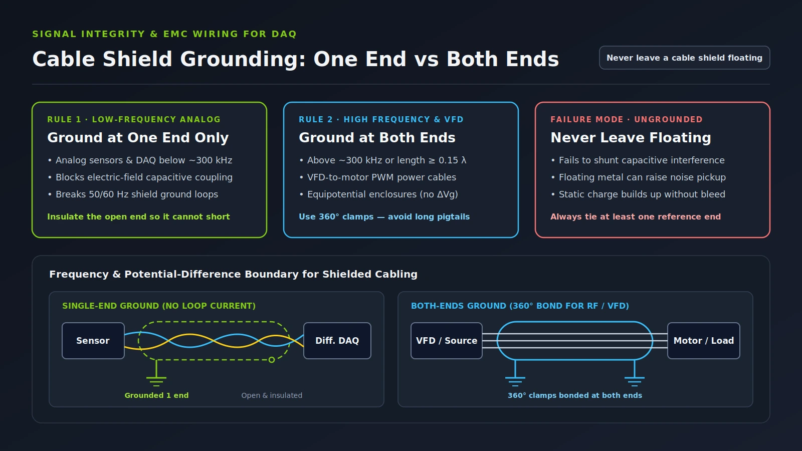
Ground a low-frequency analog DAQ cable shield at one end only whenever a ground potential difference exists between the sensor and the measurement cabinet, stopping 50 or 60 Hz ground-loop current while blocking capacitive noise. Ground both ends with 360-degree clamps above roughly 300 kHz, on VFD motor leads, or across equipotential enclosures, and do not leave a shield floating.
This independent publication (about this site) is not affiliated with National Instruments (NI) or Emerson. Related wiring guides in Sensors and DAQ cover floating DAQ input bias-resistor wiring, current-loop sensor DAQ wiring, strain-gauge amplifier signal-conditioning bandwidth, and three-wire quarter-bridge checks.
Does a shielded signal cable always need to be grounded?
Yes, a shielded signal cable must be grounded at least at one end to protect internal conductors against electric fields and capacitive coupling. Leaving conductive metal or a cable shield electrically floating near a signal path fails to drain induced charge, can actually increase capacitively coupled noise, and risks static charge buildup.
As Wikipedia’s shielded cable reference states, a cable shield must be grounded to be effective against electric fields and capacitive coupling, and the shield should remain electrically continuous across any splices. In National Instruments Application Note 025 (University of Colorado Boulder mirror), interference enters analog cabling through four principal coupling mechanisms—conductive, capacitive, inductive, and radiative—and any conductive material in the vicinity of the signal path should not be left electrically floating because capacitively coupled noise may increase.
A floating ground architecture carries a second hazard documented in the U.S. Department of Energy Electrical Systems and Safety Oversight Qualification Standard Reference Guide: static charges can accumulate on isolated conductors and eventually produce a destructive or noise-generating discharge unless a bleeding resistor connects the floating reference to ground. In short, shielded cable grounding is never optional; the real engineering choice is whether to tie one end or both ends.
Common mistake: Cutting back the foil and braid at both ends of a shielded twisted-pair cable so it “cannot form a ground loop.” An ungrounded shield removes capacitive protection and can worsen electric-field pickup on high-impedance sensor inputs.
When should a cable shield be grounded at one end only?
Ground a cable shield at one end only for low-frequency analog instrumentation and DAQ signals—generally below 300 kHz—whenever the sensor location and the receiver cabinet sit at different ground potentials. Single-point grounding shunts electric-field interference to earth while keeping the shield path open to circulating 50 or 60 hertz ground-loop current.
The U.S. Department of Energy Reference Guide notes that a single-point ground system eliminates circulating ground currents that create common-mode noise and is the standard industrial practice below 300 kHz, while noting that published crossover thresholds vary between 100 kHz and 10 MHz depending on the installation and equipment manufacturer. NASA Reference Publication 1368 (MEDIC Handbook) likewise flags low-frequency, high-load-impedance circuits as the main exception to double-ended grounding, because low-frequency noise currents carried on a double-grounded shield couple into the measurement circuit.
Source end versus receiving end on a single-grounded shield
Published application notes disagree on which single end to tie, so match the tie point to the circuit’s reference topology rather than blindly copying one diagram:
- Source end: NI Application Note 025 specifies placing the shield between capacitively coupled conductors and connecting it to ground only at the source end.
- Receiving end: In Understanding Common-Mode Signals, Analog Devices advises connecting the shield of any shielded pair carrying balanced signals to ground at one end, usually the receiving end, whenever the transmitting-location ground carries a different noise potential.
- Load-end ground lifting: Wikipedia’s ground loop overview similarly describes breaking the shield conductor at the load end—commonly called ground lifting—to stop loop current without disconnecting the safety ground.
Whichever single end you choose, insulate the ungrounded shield end cleanly with heat-shrink tubing or electrical tape so it cannot brush against a metal terminal housing, DIN rail, or conduit wall and accidentally close a loop.
When is grounding a cable shield at both ends acceptable?
Grounding a cable shield at both ends is acceptable and recommended when signal or interference frequencies exceed roughly 300 kHz, when ground cable length approaches 0.15 of the signal wavelength, when both cabinets share a low-impedance equipotential ground with no substantial potential difference, or on shielded VFD motor power leads.
According to the U.S. Department of Energy Reference Guide, a single-point ground can no longer act as a low-impedance reference once equipment dimensions or ground cable lengths approach 0.15 of the signal wavelength. Above 300 kHz or on long high-frequency ground runs, a multi-point ground system avoids high-frequency standing-wave effects even though it requires corrosion-resistant, vibration-proof bonds and careful control of ground loops.
NASA Reference Publication 1368 treats grounding cable shields at both ends as the baseline EMC rule for aerospace harnesses so the shield remains effective against high-frequency electromagnetic fields, while emphasizing that shields should never intentionally carry signal current (with coaxial cable as the exception, restricted to signals whose lowest component sits above approximately 100 kHz). Analog Devices’ Understanding Common-Mode Signals confirms that grounding both ends is also acceptable on balanced shielded twisted pairs—including shielded RS-422 and RS-485 links—when no substantial ground potential difference exists between the two ground locations; RS-485 application guidelines specify connecting the shield to earth ground either directly or through a fusible resistor at one or both ends.
| Grounding strategy | Typical frequency band | Ground potential difference condition | Primary noise mechanism controlled | Key limitation or requirement |
|---|---|---|---|---|
| One end only (single-point) | Below 300 kHz (crossover cited from 100 kHz to 10 MHz) | Different ground potentials between cabinets or sensors | Capacitive electric-field pickup without 50 to 60 Hz shield loop current | Loses low-impedance ground behavior near 0.15 signal wavelength; insulate open end |
| Both ends (multi-point) | Above 300 kHz, RF, or VFD PWM motor outputs | Equipotential enclosures or dedicated HF/VFD return path | High-frequency radiated EMI and switching common-mode currents | Can carry large low-frequency loop current if ground potential difference exists; requires 360-degree clamps |
| Double-shielded hybrid (inner and outer shields at opposite ends) | Low-frequency signal in high-RF environment | DC ground potential difference present alongside RF fields | Blocks DC/60 Hz ground loop while acting grounded at both ends at RF | Requires double-shielded cable with DC isolation between inner and outer layers |
| Floating (ungrounded at both ends) | Not recommended for signal shielding | Any condition | None for electric fields | Can increase capacitive noise pickup and allow static charge buildup |
How does double-ended shield grounding create a ground loop?
Grounding a cable shield at both ends creates a closed conductive loop through the building earth path; any ground potential difference between the two ends or stray 50 or 60 hertz magnetic flux drives circulating current along the shield, which then inductively couples noise directly into the enclosed signal wires.
Wikipedia’s ground loop reference explains that stray magnetic fields from nearby AC utility wiring oscillating at 50 or 60 hertz pass through closed ground loops and induce alternating currents by electromagnetic induction. Even without external magnetic flux, two cabinets connected to separate building ground points frequently sit at different potentials, and NI Application Note 025 notes that ground potential differences on the order of 1 V can exist between grounds.
That small voltage drives surprisingly large shield current because braided copper shields have very low resistance. In NI Application Note 025, a 1 V potential difference across a 0.5 ohm shield forces 2 A of ground current through the shield. Over a 10-ft cable with mutual inductance M equal to 1 microhenry per foot at 60 Hz, that 2 A shield current induces 7.5 mV into the signal circuit. On a 10-V range, 12-bit data acquisition system, 7.5 mV equals 3.1 LSB of interference, reducing effective measurement performance roughly to that of a 10-bit acquisition system.
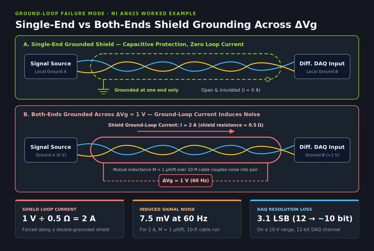
| Parameter in NI AN025 worked example | Published value | Engineering impact on the DAQ channel |
|---|---|---|
| Ground potential difference between ends | 1 V | Drives circulating current whenever both shield ends are bonded |
| Cable shield resistance | 0.5 ohm | Low impedance turns a 1 V difference into high shield current |
| Induced shield ground-loop current | 2 A | Flows directly alongside the internal signal conductors |
| Line frequency and cable run | 60 Hz over 10 ft | Typical power-frequency interference across a short bench or cabinet run |
| Mutual inductance between shield and pair | 1 microhenry per foot | Magnetically couples shield current into the signal circuit |
| Resulting induced signal noise voltage | 7.5 mV | Adds directly to low-level analog sensor readings |
| Resolution loss on 10-V, 12-bit DAQ | 3.1 LSB (roughly 10-bit effective) | Consumes roughly two bits of converter dynamic range |
Never attempt to break a ground loop by defeating the protective safety ground pin on a mains power cord or using a cheater plug. As Wikipedia’s ground loop guide warns, disconnecting the safety ground conductor leaves equipment enclosures ungrounded and creates an electric shock hazard.
What shield grounding techniques work best for twisted-pair DAQ cables?
For analog DAQ channels, pair a balanced shielded twisted-pair cable with a differential input amplifier, ground the shield at one end for low-frequency measurements, and use 360-degree circumferential clamps or RF backshells instead of long pigtails whenever high-frequency interference is present.
Twisted pair geometry and differential balance
Copper and aluminum cable shields block electric fields and electromagnetic radiation, but Analog Devices’ Understanding Common-Mode Signals and NI Application Note 025 both emphasize that copper and aluminum are ineffective against low-frequency 50 to 60 Hz magnetic fields (steel’s higher permeability helps roughly below 100 kHz, yet still fails to block power-line magnetic fields well). Because shielding low-frequency magnetic flux is impractical on flexible cables, twisted-pair geometry does the heavy lifting: twisting minimizes the enclosed signal loop area and cancels magnetically induced voltages across alternating twists.
NI Application Note 025 classifies twisted pairs and shielded twisted pairs as balanced cables—both conductors share equal impedance to ground—whereas coaxial cable is unbalanced because its center wire and outer braid have different capacitances to ground (and as Wikipedia’s shielded cable article contrasts, coaxial cable uses its shield as a signal return path while twinax does not). When a balanced shielded twisted pair feeds a differential DAQ amplifier, residual pickup appears equally on both inputs as a common-mode voltage Vcm = (V+ + V-) / 2 and is rejected according to the amplifier’s common-mode rejection ratio, CMRR (dB) = 20 log (Differential Gain / Common-Mode Gain), provided each input stays inside the device’s common-mode range (for bias-return wiring on floating sources, see floating DAQ input wiring).
360-degree shield bonding versus pigtails and hybrid schemes
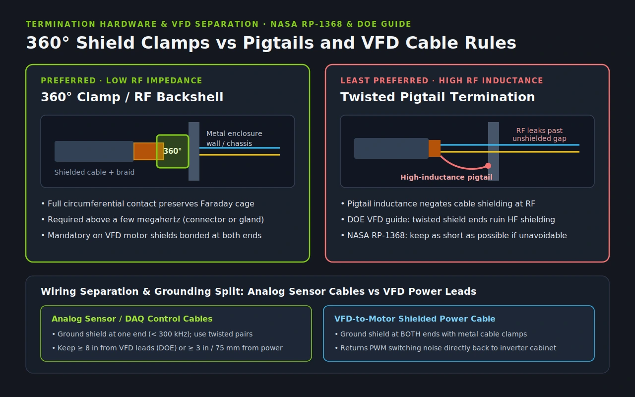
How you connect the shield to ground matters as much as which end you ground. NASA Reference Publication 1368 compares two termination styles:
- 360-degree circumferential termination: Clamping the full perimeter of the braid to a conductive backshell, enclosure wall, or EMC cable gland delivers a low-impedance path and preserves enclosure shielding integrity. Wikipedia’s shielded cable entry specifies circumferential bonding through connectors or cable glands for signals above a few megahertz.
- Pigtail termination: Twisting a shield into a single drain lead is the least preferred method because pigtail inductance at RF frequencies negates cable shielding effectiveness. If a screw terminal forces a pigtail connection, NASA RP-1368 instructs keeping the pigtail as short as possible.
When a low-frequency DAQ channel suffers simultaneously from ground potential differences and strong RF interference, three proven techniques help without creating a 60 Hz loop:
- Double-shielded hybrid grounding: NASA Reference Publication 1368 illustrates grounding the outer and inner shields each at one opposite end; the two layers remain isolated at DC to stop low-frequency loop currents, while inter-shield capacitance couples them at high frequencies so the cable behaves as if grounded at both ends against RF fields.
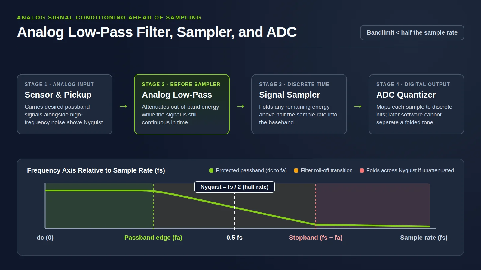
- Load-end resistive damping or RF filtering: Wikipedia’s ground loop guide notes that placing a small resistor of about 10 ohms in the shield at the load end reduces magnetically induced loop current. Meanwhile, NI Application Note 025 recommends simple passive R-C low-pass filters at the receiver end of long cables to prevent high-frequency RF pickup from demodulating into baseband offsets via audio rectification in IC junctions.
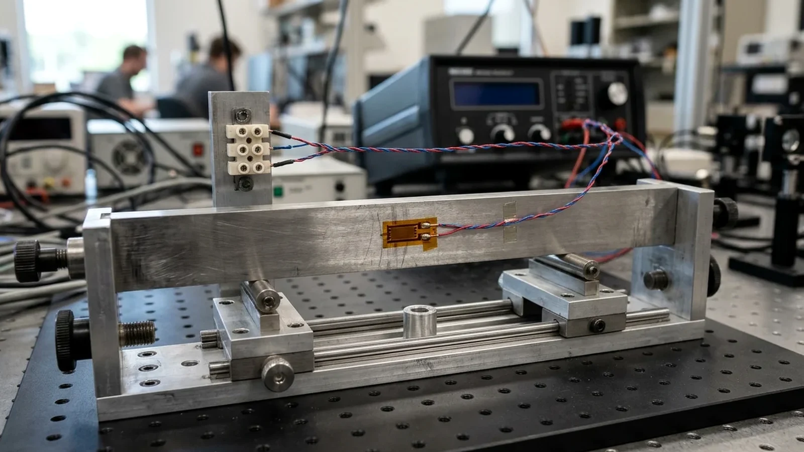
- Physical separation and strain-gauge or current-loop checks: Keep low-level sensor cables away from high-current wiring, and verify bridge or loop architecture using three-wire quarter-bridge checks and current-loop sensor DAQ wiring before blaming shield placement for a wiring offset.
How does VFD or power cable shield grounding differ from analog sensor cables?
VFD motor power cables reverse the low-frequency analog rule: their shields should be grounded at both ends using 360-degree metal cable clamps instead of twisted shield pigtails so high-frequency switching noise current returns directly to the inverter cabinet rather than radiating into nearby DAQ cables.
As detailed in the U.S. Department of Energy Reference Guide, abrupt voltage transitions set by inverter semiconductor rise and fall times make VFD output terminals an inherent source of conducted and radiated EMI. Connecting the VFD to the motor with a shielded power cable grounded at both ends—with solid electrical contact from the mounting plate through installation screws to the metal VFD cabinet—forces high-frequency noise currents back to the inverter through the shield before they disperse across plant ground structures. The DOE guide specifically warns that cable clamps should be used instead of twisted shield ends, because twisting the shield ruins high-frequency shielding effectiveness.
To keep VFD switching noise out of adjacent DAQ inputs, combine opposite shield strategies with physical spacing:
- Control and sensor spacing from VFD leads: The U.S. Department of Energy Reference Guide specifies maintaining at least 8 inches of separation between control and power wires in open air, conduit, or cable trays, twisting control leads for balanced capacitive coupling, and adding common-mode chokes or optical isolation where needed.
- General heavy power separation: Wikipedia’s shielded cable reference cites keeping data or signal cables physically separated by at least 3 inches (75 mm) from parallel heavy power circuits.
- Medium- and high-voltage power cables: Above 2000 volts, power cable shields (copper or aluminum tape or conducting polymer) equalize electric stress and prevent shock, and are typically grounded at each end and at splices; where single-point grounding is applied on high-current circuits, Wikipedia’s shielded cable reference notes that IEEE 422 and IEEE 525 limit maximum recommended shield potential rise to 25 volts. For generating-station instrumentation and control systems, the U.S. Department of Energy Reference Guide points to IEEE Std 1050-1996 for signal cable shield grounding practices that balance personnel safety with noise immunity.
| Cable class | Shield grounding rule | Termination method | Routing and safety constraint |
|---|---|---|---|
| Analog DAQ sensor cable (below 300 kHz) | One end only when ground potential difference exists | Short drain or 360-degree clamp at reference end; insulate open end | Keep at least 8 inches from VFD power leads (DOE) or 3 inches (75 mm) from heavy parallel power |
| RF or high-frequency signal cable (above 300 kHz) | Both ends (or coax above 100 kHz) | 360-degree RF backshell or circumferential cable gland | Maintain continuous shielding across connectors and splices; avoid pigtails |
| VFD inverter-to-motor power cable | Both ends (drive chassis and motor frame) | 360-degree metal cable clamps instead of twisted shield ends | Returns high-frequency PWM noise current to inverter; ensure metal-to-metal mounting contact |
| Medium- and high-voltage power cable (over 2000 V) | Each end and splices for shock and stress control | Grounded tape or polymer shield with stress-relief cones | Single-point ground limited to 25 V shield potential rise per IEEE 422 and IEEE 525 |
Pre-commissioning shield grounding checklist
Before powering a DAQ cabinet or logging production channels, confirm each check in order so a miswired shield does not mask transducer behavior:
| Inspection step | What to verify at the panel | Pass condition |
|---|---|---|
| 1. Signal frequency and cable type | Confirm bandwidth below or above 300 kHz and whether conductors are twisted pair | Analog DAQ sensors use balanced shielded twisted pair rather than unbalanced coax |
| 2. Ground potential check | Verify whether sensor and DAQ enclosures share one equipotential bond or separate earths | Separate earths use single-end shield grounding; equipotential RF or VFD runs use both ends |
| 3. Open-end insulation | Inspect the ungrounded end of every single-ended analog shield | Foil and drain wire are trimmed and insulated with heat-shrink so zero contact occurs |
| 4. Termination geometry | Check shield clamp or drain length at the grounded end | 360-degree clamp on VFD and RF cables; shortest possible drain where screw terminals are unavoidable |
| 5. Power-cable separation | Measure tray and conduit spacing from VFD motor leads and AC power feeders | At least 8 inches from VFD power (DOE) and at least 3 inches (75 mm) from heavy parallel power |
| 6. Protective earth integrity | Confirm mains safety ground conductors remain intact on all chassis | Zero lifted safety pins; ground loops are broken strictly on low-voltage signal or shield paths |