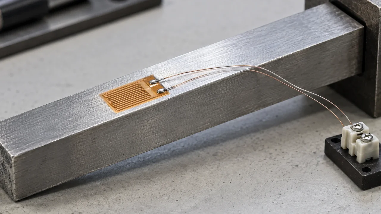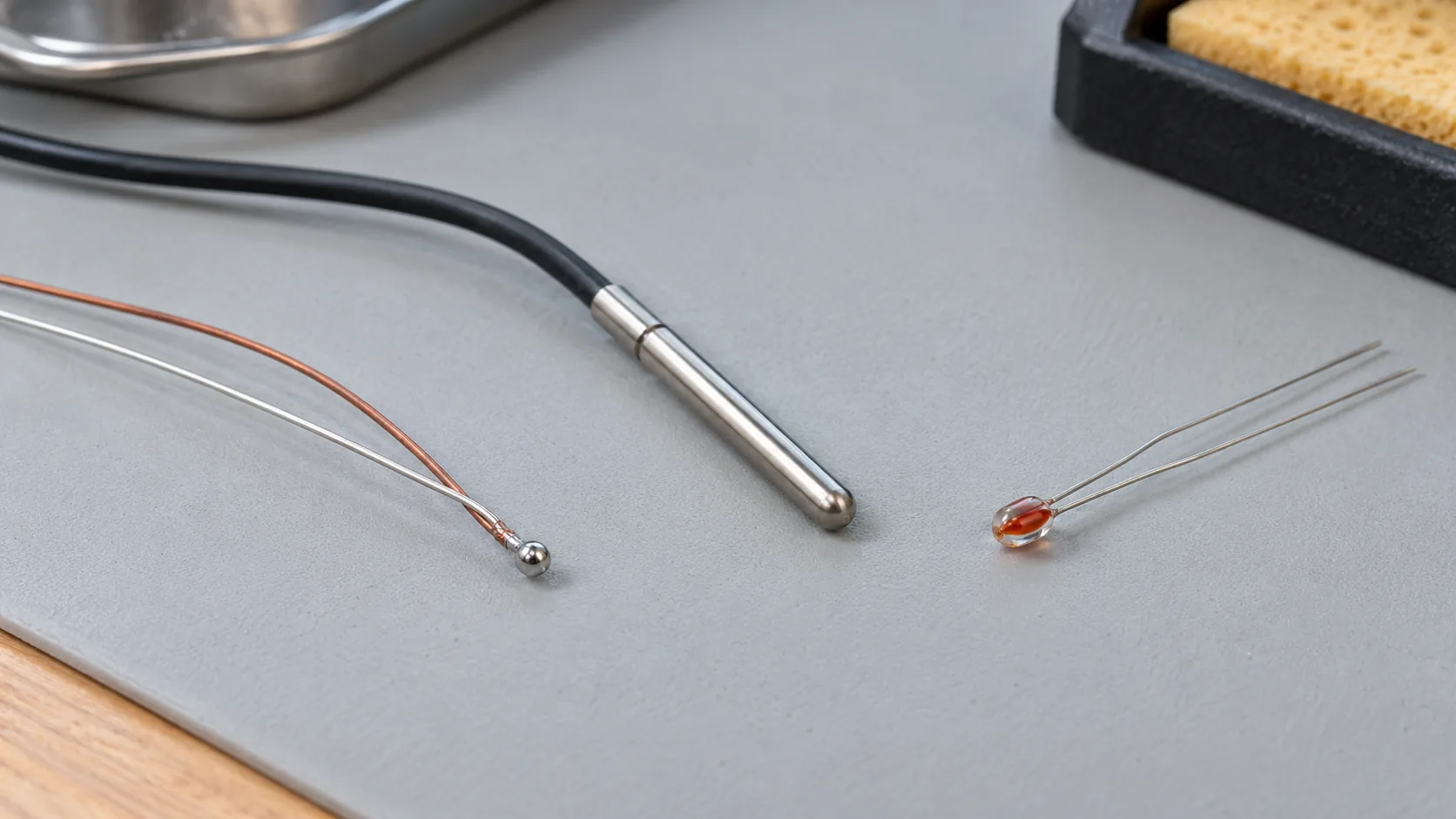
A DAQ channel wired for the wrong electrical quantity will log a confident temperature that belongs to a different sensor. Choose the sensor from the temperature span and the tolerance band, then give the channel the voltage or the resistance measurement that sensor produces.
NIST Monograph 175 (April 1993) tabulates thermocouple voltage with the reference junction at 0°C. IEC 60751:2022, in the preview read for this page, gives a Pt100 a tolerance formula and a separate validity range for wire-wound and film construction. TI’s SBAA338A example uses an NTC only from −25°C to 100°C. The cold-junction placement note is the next step once a thermocouple is the choice. Acquisition timing sits in the DAQ sample-rate worksheet. This page is one of the sensor and DAQ notes. It is an independent technical publication, and the about page states the site’s separation from Emerson and National Instruments.
| Sensor on the channel | What you measure | Dominant failure mode | Prevention |
|---|---|---|---|
| Type K thermocouple | Voltage. NIST tables use a 0°C reference | Terminal temperature treated as 0°C, or the wrong type polynomial | Compensate at the copper transition. Confirm the letter type |
| Type T thermocouple | Voltage. ASTM E230-87 standard tolerance, as quoted by NIST, is ±1°C or ±0.75%, whichever is greater, from 0°C to 350°C | Protected-wire limit ignored for the gauge in hand | AWG 14 protected limit in that citation is 370°C. AWG 24 or 28 is 200°C |
| Pt100 class A | Resistance. ±(0.15 + 0.002|t|) °C | Class A used outside the film or wire-wound column | Film thermometer: −30°C to +300°C. Wire-wound thermometer: −100°C to +450°C |
| Pt100, two-wire | Resistance plus both leads | Lead ohms left in the reading | IEC 60751:2022 says to subtract two-wire lead resistance. A matched three-wire or a four-wire circuit removes it in the measurement |
| NTC divider | Divider voltage, ratiometric to the ADC reference | Beta value used outside the datasheet span | TI’s worked example is −25°C to 100°C, 100 kΩ at 25°C, B(25/85) = 3977 |
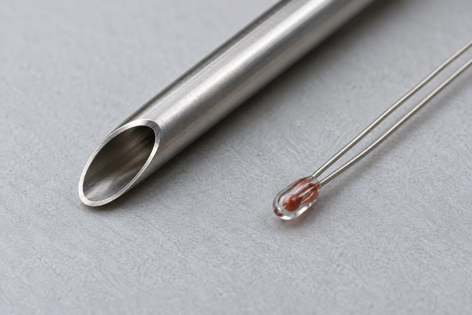
Thermocouple tolerance is a percentage with a floor
NIST Monograph 175 gives reference functions for letter-designated types B, E, J, K, N, R, S, and T. The functions express thermoelectric voltage against temperature with the reference junctions at 0°C. The span of those functions runs from −270°C for types E, K, N, and T to 1820°C for type B.
The monograph records the initial calibration tolerances in ASTM E230-87, as printed in the 1992 Annual Book of ASTM Standards. Those sentences are the 1987 edition as NIST quoted it in 1993. They are the numbers used below. A current ASTM book can differ, and this page does not substitute for it.
For type K, the standard tolerance is ±2.2°C or ±0.75%, whichever is greater, from 0°C to 1250°C. From −200°C to 0°C it is ±2.2°C or ±2%, whichever is greater. Special tolerances from 0°C to 1250°C are about half the standard tolerance. Wire supplied to the positive-range tolerance can miss the negative-range tolerance, and NIST says to specify the cold range at purchase when you need it. The suggested upper temperature for a protected type K in a conventional closed-end tube is 1260°C on AWG 8 (3.25 mm), 1090°C on AWG 14, 980°C on AWG 20, 870°C on AWG 24 or 28, and 760°C on AWG 30. NIST calls those limits a rough guide. They do not apply to compacted mineral-insulated cable. In air above about 750°C both legs oxidize. Green-rot of the positive leg, from preferential chromium oxidation in a low-oxygen atmosphere, is most serious from 800°C to 1050°C.
For type T, the standard tolerance is ±1°C or ±0.75%, whichever is greater, from 0°C to 350°C, and ±1°C or ±1.5%, whichever is greater, from −200°C to 0°C. The protected upper limit is 370°C on AWG 14 (1.63 mm), 260°C on AWG 20, 200°C on AWG 24 or 28, and 150°C on AWG 30. The same closed-end-tube caveat applies.
At 100°C the type K percentage is the smaller number, so the floor wins:
0.0075 × 100°C = 0.75°C
tolerance = greater of 2.2°C and 0.75°C = ±2.2°C
At 500°C the percentage wins:
0.0075 × 500°C = 3.75°C
tolerance = greater of 2.2°C and 3.75°C = ±3.75°C
Type T at 100°C, inside the 0°C to 350°C column:
0.0075 × 100°C = 0.75°C
tolerance = greater of 1°C and 0.75°C = ±1°C
The IEC webstore page for IEC 60584-1:2013 says that edition specifies reference functions and tolerances for the letter-designated types, that the third edition cancels and replaces the second edition published in 1995, and that IEC 60584-1:1995 and IEC 60584-2:1982 have been merged. The free page states that scope. It does not print the tolerance table, so the worked numbers in this section stay with the ASTM E230-87 text that Monograph 175 actually quotes.
A bench terminal is rarely an ice bath. The channel adds the voltage that belongs to the terminal temperature, using the same letter type. Where that sensor sits is the subject of the cold-junction note. If the thermocouple floats relative to the module, the floating-input wiring note is the electrical check beside the thermal one.
Rule of thumb: If the process is above 450°C, both IEC 60751:2022 class A thermometer columns have already ended (wire-wound at +450°C, film at +300°C). A type K thermocouple still has an ASTM E230-87 standard tolerance stated through 1250°C. At 500°C that tolerance is ±3.75°C.
Takeaway: Write the letter, the tolerance at the working temperature, the wire gauge, and the location of the reference junction.
A Pt100 class is a formula inside a temperature column
IEC 60751:2022 defines the temperature coefficient as
α = (R100 − R0) / (R0 × 100°C) = 3.851×10⁻³ °C⁻¹A platinum resistor with R0 = 100 Ω is a Pt100. From 0°C to 850°C the preview gives
Rt = R0 (1 + A t + B t²)
A = 3.9083×10⁻³ °C⁻¹
B = −5.775×10⁻⁷ °C⁻²
At 100°C:
Rt = 100 × (1 + 3.9083×10⁻³ × 100 − 5.775×10⁻⁷ × 100²) = 138.5055 ΩThe slope at 0°C is R0 × A:
dR/dt = 100 × 3.9083×10⁻³ = 0.39083 Ω/°COne ohm of lead resistance that you leave in a two-wire reading is
Δt = 1 / 0.39083 = 2.56°CTable 2 of the same preview sets thermometer classes. Class A is ±(0.15 + 0.002|t|) °C. At 100°C that is ±0.35°C. The wire-wound class A column runs from −100°C to +450°C. The film class A column runs from −30°C to +300°C. Class B is ±(0.3 + 0.005|t|) °C, so ±0.8°C at 100°C. Wire-wound class B runs from −196°C to +600°C. Film class B runs from −50°C to +500°C. Class AA is ±(0.1 + 0.0017|t|) °C, film only from 0°C to +150°C, wire-wound from −50°C to +250°C.
At 500°C the class A formula is outside both class A columns. Wire-wound class B still covers 500°C:
Δt = 0.3 + 0.005 × 500 = ±2.8°CTI SBAA275A Table 1-1 prints the same class A and class B formulas, with ±0.35°C and ±0.8°C at 100°C, and a 0°C resistance of 100 ± 0.06 Ω for class A and 100 ± 0.12 Ω for class B. The note also says the valid temperature span gets smaller for the tighter classes and depends on construction. The 2022 preview is the document that splits those spans into the columns above. TI’s footnote says 1/10 DIN is an industry tolerance and is outside IEC 60751. This page leaves it there.
Clause 4.1 of the preview tells you to subtract the lead resistance between the platinum resistor and the terminals on a two-wire connection. The lead temperature coefficient can matter as well, and the standard allows that information to be supplied with the thermometer.
Rule of thumb: If a film element is above 300°C, class A (F 0,15) is outside its validity column. Use a class whose column still contains the temperature, or move to the thermocouple section.
Takeaway: Record wire-wound or film, the class, and the temperature. The formula is the band only inside that column.
Excitation current heats the resistor you are measuring
TI SBAA275A equation 14 defines the self-heating error as
ΔT = I² × R / Ewith E in mW/°C. IEC 60751:2022 clause 3.11 defines a self-heating coefficient in °C/mW, which is the reciprocal. Keep the unit that the sensor sheet uses, and invert it before you drop it into equation 14.
TI gives a typical span of 2.5 mW/°C for small thin-film elements and 65 mW/°C for larger wire-wound elements, and says the coefficient also depends on air versus water. The sensor datasheet replaces that typical span for a named part.
The note treats a Pt100 from −200°C to 850°C as about 20 Ω to 400 Ω, and it uses 1 mA through 400 Ω as the high-end case. Power and the two typical coefficients:
P = (0.001)² × 400 = 0.0004 W = 0.4 mW
ΔT_film = 0.4 / 2.5 = 0.16°C
ΔT_wire = 0.4 / 65 = 0.00615°C
TI’s statement that this power stays under 0.01°C belongs to the larger coefficient. On the 2.5 mW/°C film the same 0.4 mW is 0.16°C. That is nearly half of the ±0.35°C class A band at 100°C:
0.16 / 0.35 = 0.46The note lists IDAC settings of 10, 50, 100, 250, 500, 750, 1000, 1500, and 2000 µA, and says most excitation currents should stay below 1 mA because of self-heating. A larger current lifts the signal above the noise. The other limit is compliance: when the IDAC pin voltage rises too close to the supply, the current falls and the ratiometric assumption goes with it.
In the two-wire ratiometric circuit, the same current runs through the Pt100 and the reference resistor, so it cancels:
R_RTD = R_REF × code / (2²³ × gain)That is TI equation 18 for the converter width they use in that section. Current accuracy drops out when the current that heats the sensor is the current that develops the reference, and when none of it leaks. Reference-resistor error remains in the resistance reading at the same proportion. Lead resistance, which the note says you can add into the R_RTD term, does not cancel.
A three-wire circuit uses a second current so that matched lead resistances and matched currents drop out. Residual mismatch stays. TI’s chopping measurement swaps the two current sources and averages the pair. A four-wire circuit puts excitation on one pair and the sense measurement on the other, so the sense leads carry negligible current. TI calls the four-wire result the most accurate, and the one that uses the most connections.

Rule of thumb: If thin-film ΔT at the highest resistance is a large share of the tolerance band, cut the current before you buy a tighter class. At 1 mA and 400 Ω, 0.16°C already occupies 46% of a ±0.35°C class A band at 100°C. Half the current cuts the heat by four, because power follows I²:
(0.5 / 1)² = 0.25
0.16°C × 0.25 = 0.04°C
Takeaway: Record the current, the resistance at the hot end, E and its unit, and whether the wiring is two-wire, three-wire, or four-wire.
An NTC divider is a span with a published beta
TI SBAA338A, revised June 2022, sizes a single-ended SAR input for −25°C to 100°C. The example thermistor is 100 kΩ at 25°C with B(25/85) = 3977. The divider is powered from AVDD, and AVDD is the converter reference, so supply movement is common to the signal and the reference.
R_NTC = R_25 × exp(B × (1/T − 1/298.15))T is in kelvin. The note prints the ends of the span and the series resistor:
T = 248.15 K (−25°C): R = 1,469.744 kΩ
T = 373.15 K (100°C): R = 6.849 kΩ
R1 = √(6.849 × 1,469.744) = 100.333 kΩ
They select 100 kΩ. Substituting B = 3977 into the equation reproduces those two printed resistances. The parallel of 100 kΩ and 1,469.744 kΩ is the 93.627 kΩ they use as the worst-case source resistance for settling. In that ADS7142 simulation, C1 lands at 100 pF for a 10 kHz target. A different converter uses its own sample-and-hold capacitor and acquisition time.
The note treats a 1% series resistor as the usual match to thermistor tolerance, and a tighter resistor when the requirement is tighter. It does not publish an interchangeability class comparable to IEC 60751 Table 2.
Divider current is the heating path. On the 3.3 V supply in the example, with R1 = 100 kΩ:
I_cold = 3.3 / (1,469.744 kΩ + 100 kΩ) = 2.10 µA
P_cold = I² × 1,469.744 kΩ = 6.5 µW
I_hot = 3.3 / (6.849 kΩ + 100 kΩ) = 30.9 µA
P_hot = I² × 6.849 kΩ = 6.5 µW
SBAA338A does not give a self-heating coefficient, so these microwatts stay as power until the thermistor datasheet supplies °C/mW or mW/°C. They are far below the 0.4 mW Pt100 example, which is a comparison of the two published circuits, not a claim that every NTC runs this cool.
Rule of thumb: If the span goes above 100°C or below −25°C, this B(25/85) = 3977 example is outside the range TI calculated. Use a beta whose datasheet range covers the span, or return to a Pt100 or thermocouple whose validity column you have already checked.
Takeaway: Write R25, B, the two end temperatures, R1, and the converter the settling capacitor was sized for.
The lead ohm can dwarf the class you paid for
Put the 100°C numbers from the sections above on one line. Type K standard tolerance is ±2.2°C. Type T standard tolerance is ±1°C. Class A, inside its column, is ±0.35°C. One ohm of two-wire lead, at the 0°C slope, is 2.56°C.
The lead is larger than the class A band. A class AA element, ±(0.1 + 0.0017|t|) °C, still sits on that lead if the wiring is two-wire and nobody subtracts it. IEC clause 4.1 is the subtraction. TI’s three-wire and four-wire circuits are the measurement that makes the subtraction unnecessary when the leads and the currents match.
Self-heating spends part of the same band. At 1 mA and 400 Ω, the thin-film 0.16°C is 46% of ±0.35°C before the resistor’s own tolerance is added. Moving from 1 mA to 0.5 mA, with the same 400 Ω and the same 2.5 mW/°C, leaves 0.04°C. The signal amplitude falls with the current, which is why TI pushes the current up until self-heating or compliance says to stop.
A thermocouple polynomial on an RTD channel, or an excitation current on a thermocouple junction, reads the wrong quantity. The correction is a wiring and configuration change and a repeat of the tolerance check. This page has no prices.
Takeaway: At 100°C, a forgotten 1 Ω lead is 2.56°C on a sensor whose class A band is 0.35°C.
Copy one selection row
| Field | What to write |
|---|---|
| Temperature span | Minimum and maximum, with the unit |
| Sensor | Type K, type T, Pt100, or the NTC R25 and B |
| Validity column | ASTM range and gauge, or IEC wire-wound versus film class |
| Tolerance at the working point | The greater-of result, or ±(a + b|t|), with the arithmetic shown |
| Electrical quantity | Voltage, resistance, or divider voltage |
| Excitation | Current, or none for the thermocouple |
| Self-heating | I, R, E, unit, and ΔT |
| Leads | Two-wire with a subtracted ohm, three-wire, or four-wire |
| Reference junction | Ice point, or the terminal sensor and its location |
| Next check | Cold-junction placement, floating-input bias, or the sample-rate worksheet |
How this page was checked
NIST Monograph 175, April 1993, supplies the reference-junction condition, the type K and type T tolerance sentences from ASTM E230-87 in the 1992 Annual Book, the protected-wire temperature limits, and the oxidation and green-rot limits quoted above. The IEC webstore page for IEC 60584-1:2013, read on 20 October 2026, supplies the scope sentence, the statement that the third edition cancels and replaces the 1995 edition, and the statement that IEC 60584-1:1995 and IEC 60584-2:1982 have been merged. The tolerance arithmetic uses the ASTM sentences, because that webstore page does not print the IEC table.
The SIST preview of IEC 60751:2022 supplies alpha, the Callendar constants A and B, Table 2 class formulas and validity columns, the two-wire lead instruction in clause 4.1, and the °C/mW definition in clause 3.11. TI SBAA275A, revised March 2023, supplies equation 14, the 2.5 and 65 mW/°C typical coefficients, the 20 Ω to 400 Ω span, the IDAC list, equation 18, and the three-wire and four-wire lead behavior. TI SBAA338A, revised June 2022, supplies the NTC example, the printed resistances, R1, and the 3.3 V divider. The 2.56°C lead, the 0.16°C and 0.00615°C self-heating results, the 0.04°C half-current case, and the 6.5 µW divider powers are the arithmetic on those published inputs. No sensor was measured for this page.