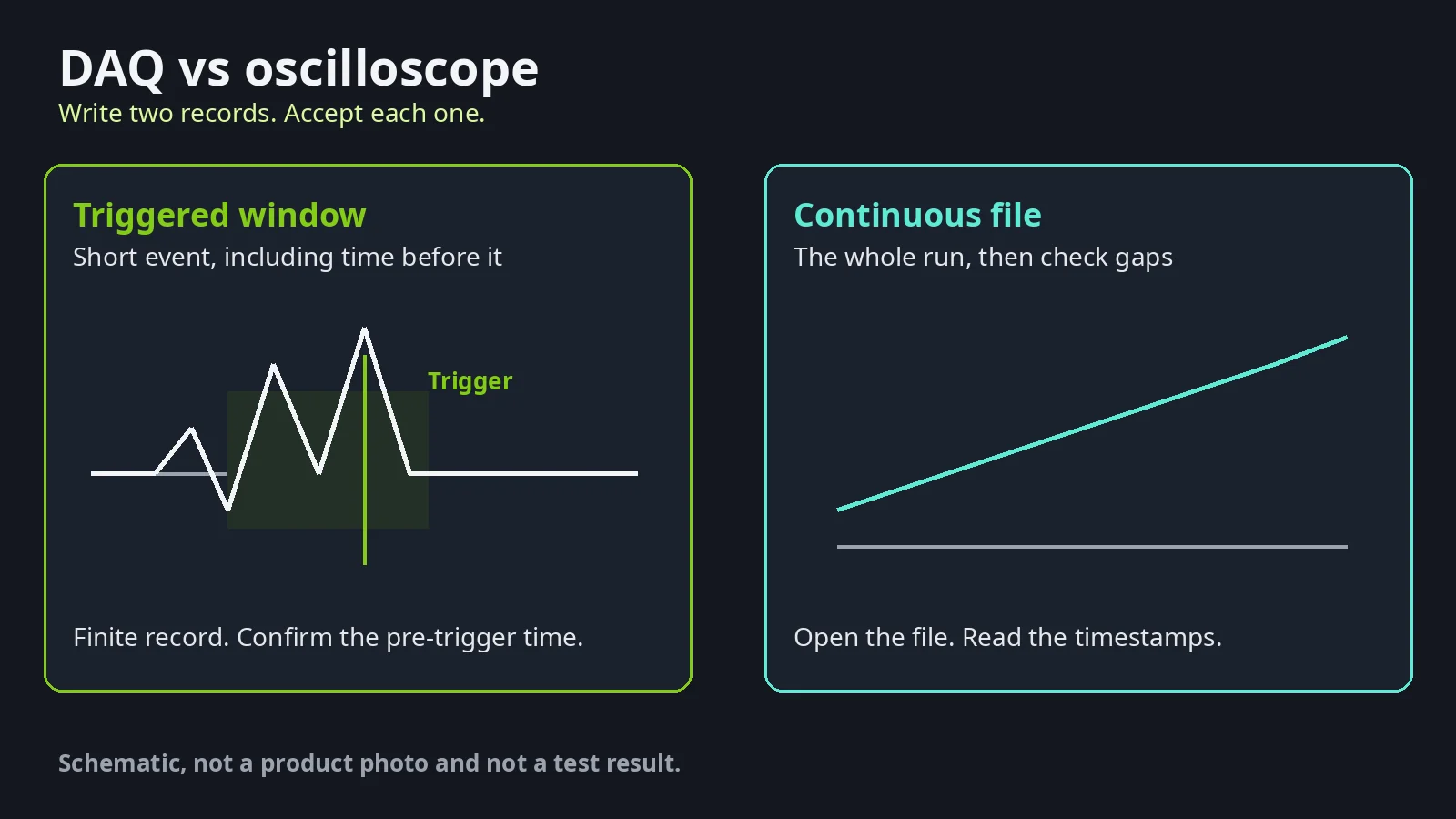
Picking a scope for a file that has to run for hours, or a logger for a brief control glitch, wastes the setup and still misses the fault. Keep a triggered waveform when the record is a short event, and keep a continuous data-acquisition file when the record is the whole run.
This page is a requirements record you can hand to a supplier. It compares instrument classes on the same checks: trigger, continuous file, storage, and input isolation. It does not rank models or quote prices. Compiled from public sources by an independent publication (about this site). This site is not affiliated with National Instruments (NI) or Emerson.
If you are still choosing the sensor and the plant network, use the industrial IoT sensor guide. This page starts after that signal exists.
| Record to keep | Instrument class to ask for | Acceptance check |
|---|---|---|
| A short event, including time before the trigger | Oscilloscope, or DAQ software that stores a triggered record | The saved record contains the pre-trigger interval you wrote down |
| A file that covers the whole run | DAQ or logger whose manual states continuous recording | Timestamps cover the run, with no gap larger than your limit |
| Both the event and the long file | Two lines on the requirements record | Each line passes on its own |
Which record are you trying to keep?
Name the record before you name the box. A short event needs a trigger and a finite window. A shift, a soak, or a trend needs a file that is still there at the end. Asking one instrument for both is a third job, and it stays two lines until the manual says the two captures can run together.
Readers already describe the split in those terms. On 20 March 2014 an All About Circuits thread asked for help catching intermittent machine-control glitches: noise on communication lines, brief digital dropouts, analog signals that go under or over a limit, and the sequence of several digital and analog signals. The same post also asked for a strip-chart over long periods, with a way to zoom in on a blip. Those are two records. A Chief Delphi request on 17 December 2012 asked for a portable scope that can trigger, rather than free-run, while watching PWM to servos or motor controllers, and it added “no PC needed.”
A reply there on 27 December 2012 quoted an NI description: data acquisition measures an electrical or physical phenomenon such as voltage, current, temperature, pressure, or sound with a computer, and a DAQ system consists of sensors, DAQ measurement hardware, and a computer with programmable software. A following reply pointed out that a DAQ had not been suggested because the original request ruled out a PC. If your logger must work with no computer attached, that constraint belongs on the requirements record. It is not a reason to skip the trigger check.
Takeaway: Write the record first — short triggered window, continuous file, or both as two lines.
How does a trigger record differ from a continuous log?
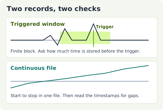
A trigger record is a finite window parked on an event. A continuous log is a file that spans the run. The window can be perfect and the file still full of gaps, or the file can be complete and the window still missing the moment before the trigger.
An obsolete DATAQ page for the DI-770, in that company’s obsolete-products section, describes the usual oscilloscope view as the time domain, used for amplitude, time, and phase. The same page says that instrument can compute a spectrum from stored time-domain segments of up to 16K samples, and that the spectrum display can run at the same time as the oscilloscope view. Those figures belong to that discontinued model. Do not copy 16K samples, or “simultaneous spectrum,” onto another instrument. The useful point is the split: a time-domain window answers “what did the waveform do around this event,” and a stored segment is a finite block, not automatically a shift-long file.
A teaching lab shows the same finite-window habit on DAQ hardware. The Cornell ECE 5030 page dated 20 February 2013 assigns an NI USB-6008 capture at 10 ksamples/s on one channel, with collection durations of 0.01, 0.02, 0.05, 0.1, or 0.2 seconds, plotted like an oscilloscope. At that assigned rate, 0.2 seconds is 10,000 × 0.2 = 2,000 samples. That arithmetic uses only the lab’s settings. It is not a maximum for the USB-6008 and not a maximum for DAQ systems. This site does not sell or rank that device.
Storage is a separate test from the on-screen trace. On 1 December 2020 a Stack Exchange user of a LeCroy oscilloscope tried to sample and write to disk at 1 kHz. A logging script set to write every 1 millisecond produced a file whose points were about 100 milliseconds apart. The user attributed the delay to the time that scope needed to acquire and process, and reported that a live stream to a computer failed because of that setup’s hardware limits. One comment suggested buffering many reads and writing them in a batch. None of that is a rate for other oscilloscopes or other DAQ units. It is a reason to open the file and read the timestamps, instead of trusting the interval typed into a script.
A Test & Measurement Tips explainer published 5 February 2013 describes DAQ systems as storing information on disk, with a sensor or transducer turning the physical measurement into an electrical signal such as voltage or current, an analog-to-digital converter in the chain, and signal-conditioning hardware when the sensor does not connect directly. The archived page is thin, so this article uses only those points.
Takeaway: Accept the triggered window and the saved file as two results, even when they come from one instrument.
What should the supplier requirements record include?
Hand the supplier a filled record, not a model name. You write the event, the interval, the channels, the levels, and what “saved” means. The supplier writes the manual’s numbers next to those lines, with units. Unknown cells stay blank until the manual states them.
| Line | You fill in | Supplier copies from the manual |
|---|---|---|
| Event to see | Duration, and which signal | Sample rate and record length that cover it |
| Pre-trigger | Time to keep before the trigger | Whether pre-trigger is stored, and how much |
| Continuous interval | Start-to-stop duration | Longest gap-free file at the rate you need |
| Channels | Analog count and digital count | Inputs available at the same time |
| Signal levels | Volts, milliamps, or digital voltage | Rated range and impedance |
| Isolation | Circuit ground versus the computer port | Isolation rating, or the external barrier required |
| Unattended | Computer attached or not, and for how long | Logging with the computer disconnected |
| Saved result | Screen, instrument disk, or a file on the PC | File format and the tested write interval |
The 2014 machine-control list is a useful set of questions, not a specification of today’s products. It asked for 24 V DC and 120 V AC digital inputs, ±10 V and 0–20 mA analog, at least two analog channels, isolation from the USB port, a strip-chart with zoom, and user-set trigger conditions. The poster expected to add an opto-isolator, because the units then under review did not take those digital voltages directly and did not take AC on the digital inputs. The same post called multi-day logging with the laptop disconnected a wish, and noted that a PLC already did a coarser version of that job. Put the levels and the unattended line on the record. Leave the product limits in 2014.
Trigger text should be something a manual can answer yes or no. “When digital input 1 is high, digital input 7 is low, and analog input 3 is above analog input 1” is the shape of the combined condition in that 2014 post. If the manual has no combined trigger, say so on the line and plan another way to mark the event.
Takeaway: Leave a blank where the manual is silent. Do not fill it with a number from a different instrument.
What input and isolation checks come before the sample rate?
The sample rate does not matter if the input clips, floats, or shares a ground the module cannot accept. Match the electrical signal to an input the manual lists, then check isolation between the circuit and the computer port.
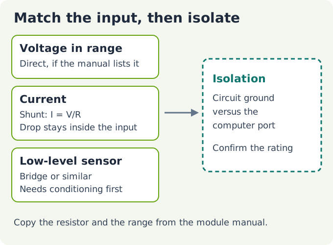
NI’s current-measurement guide, updated 7 October 2024, says the common method is indirect: measure the voltage across a precision resistor and apply Ohm’s law, I = V/R. Any resistor is acceptable in that guide only while the maximum expected current times the resistance stays inside the input range of the meter or DAQ device. A smaller resistor disturbs the circuit less and produces a smaller voltage, so resolution and circuit disturbance stay a compromise. This page does not publish a resistor value. Copy it from the module manual.
The same NI guide says that when the external circuit shares a ground with the computer that holds the DAQ device, the shunt goes as close to the ground leg as possible. Otherwise the common-mode voltage from the shunt can sit outside the device rating and can give inaccurate readings or damage the board. The guide uses two NI modules as architectures, not as a shopping list: the NI 9203 has an internal precision resistor, and the NI 9205 needs an external shunt. Confirm which architecture your module uses before you add a resistor of your own.
A single-ended wire on a differential setting fails in a quieter way. The Cornell lab tells students to use USB-6008 terminals 1 (ground) and 2 (analog input 0) for a single-ended input, and to set the input type to single-ended. The page warns of a large DC offset if that setting is left at the differential default. Check the input type in software against the terminals you actually landed, on the device you actually have.
A bridge or other low-level sensor is not a scope-probe voltage. How a strain gauge becomes a small bridge voltage is covered in the strain gauge explainer. Whether you need that strain, or a calibrated force from a load cell, is a different choice, covered in strain gauge vs load cell. Read the condition attached to any headline rate the way the profileGAUGE C.ODC spec note does: the number counts only with the channel count, the record length, and the input mode the manual ties to it.
Takeaway: Confirm range, shunt or direct input, input type, and isolation before you argue about sample rate.
How do you accept the instrument before you rely on it?
Run two checks. One proves the trigger window. One proves the file. A screen that looked right during the run is not a substitute for either file.

Test A, the window. Inject or wait for a known short pulse on the channel you care about. Trigger with the condition written on the record. Open the saved record and confirm it includes the pre-trigger time you specified, not only the time after the event. If the record is shorter than that window, the instrument failed this line even if the pulse was visible on screen.
Test B, the file. Record for the interval written on the record, at the channel count you will use in the real test. Open the file. Find the largest gap between timestamps. The line passes only when that gap is no larger than the limit you wrote down before the run. The LeCroy report is the cautionary shape: the script interval and the file interval were not the same number. Measure the file.
If you need both records, both tests have to pass. Passing Test A on a scope and Test B on a separate logger is a valid result. The requirements record should say which instrument owns which line.
Common mistake: Calling the setup done because the glitch was visible once. The long file can still skip the next one, and the saved window can still omit the pre-trigger time.
Takeaway: Pass the window and the file separately, and write which instrument owns each line.
Where do these checks stop?
These checks choose an instrument class and a pair of acceptance tests. They do not pick a model, a price, or a sample rate for a channel count this page has not calculated. They do not say that every oscilloscope fails at disk logging. They do not say that every DAQ can trigger, store pre-trigger data, or run with the computer unplugged. Hazardous-area rules, calibration certificates, and plant-network design are outside this page.
Other instrument notes on this site are listed on the blog and under test and measurement. Sensor and bridge background is under sensors and DAQ. Machine-control context sits under automation.
Takeaway: Stop when both lines are either passed or still blank. A blank is a question for the manual, not a guess.
Method and sources
Compiled on 11 October 2026 from the public pages listed at the end of this article. Forum threads are used as reader situations, not as specifications: the All About Circuits post of 20 March 2014, the Chief Delphi thread opened 17 December 2012, and the Stack Exchange report of 1 December 2020. The Cornell lab page is dated 20 February 2013 and describes one course setup. NI’s current guide shows an update date of 7 October 2024 and is quoted for measurement method, not as an endorsement. The DATAQ DI-770 page is an obsolete-product page and is not a recommendation. The Test & Measurement Tips DAQ explainer is dated 5 February 2013; only the points still readable in the archived text are used.
No figure on this page is a photograph of a customer site, a test bench, or a specific model. The drawings are schematics. This site did not run the acceptance tests. National Instruments product names appear only where those public pages name them. Nothing here is an NI or Emerson document, and nothing here is investment advice.