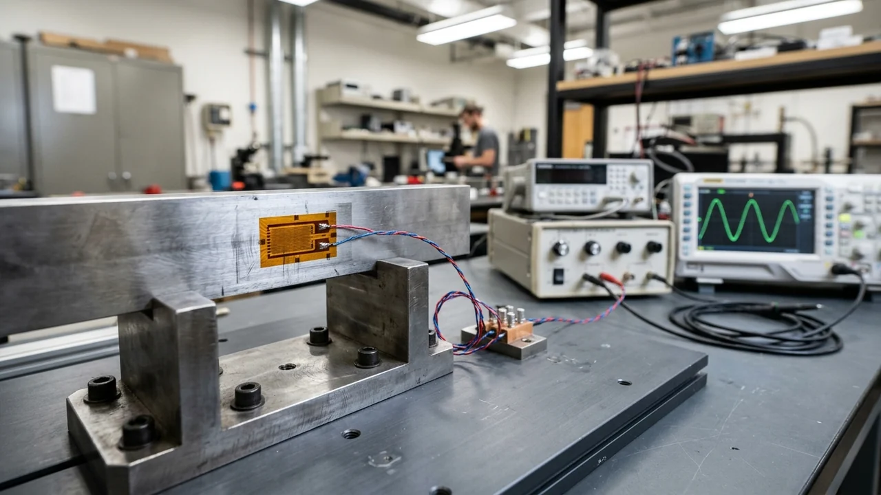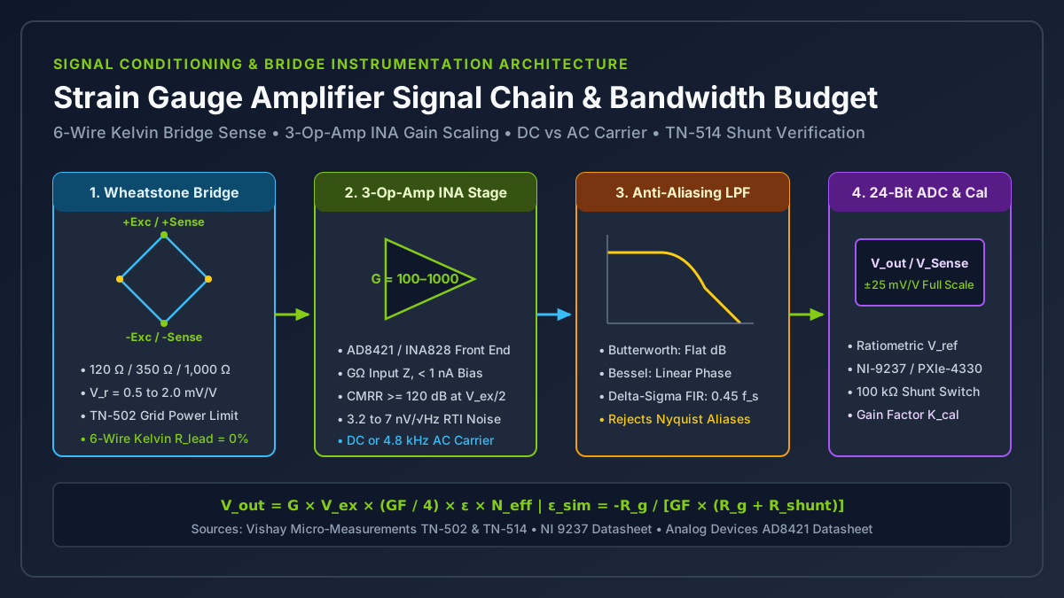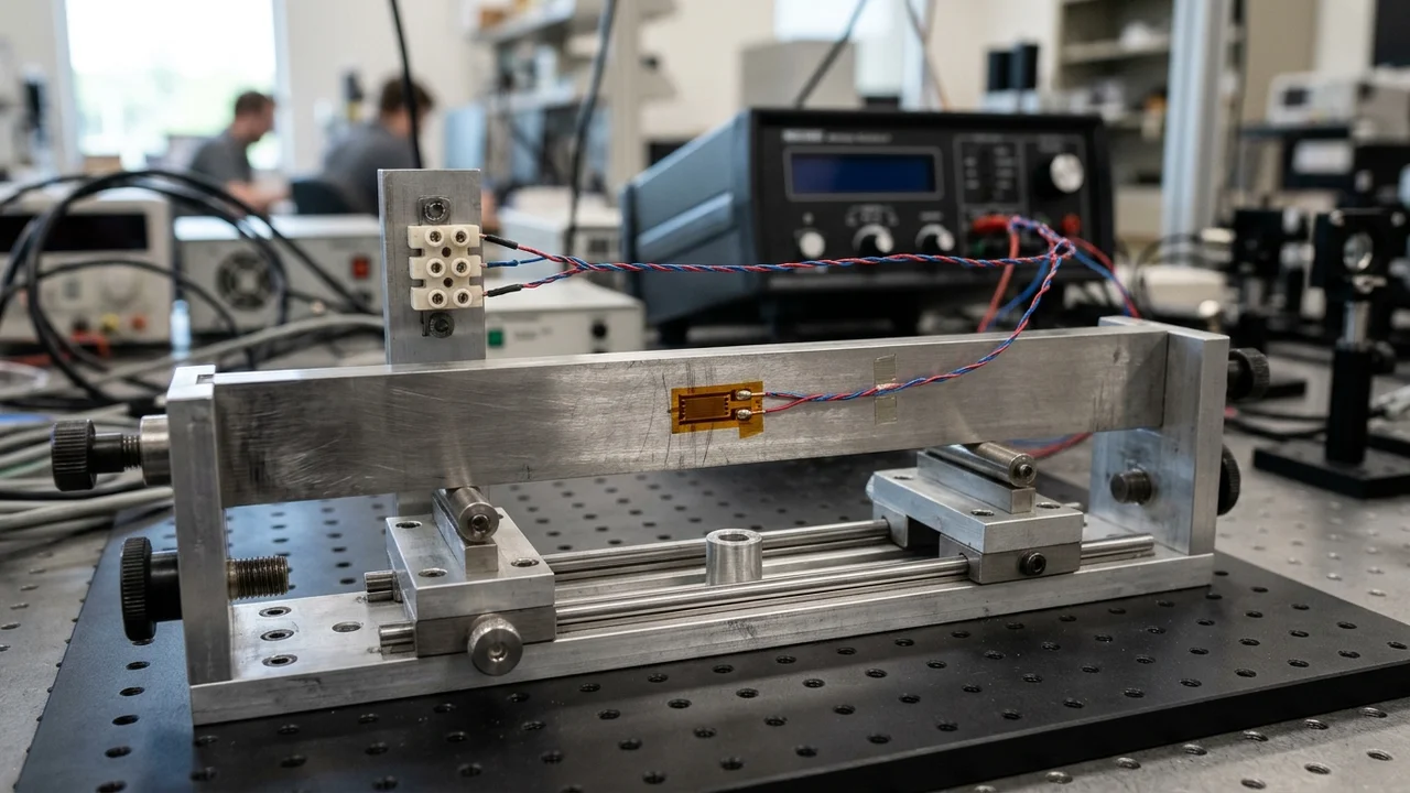
Gage factor is the transfer function of a strain gage relating resistance change to applied strain so accuracy of strain gage data can be no better than the accuracy of the gage factor, and although transverse sensitivity is usually much less than 10 % of the gage factor, large errors can occur if it is not known with reasonable precision.
When a strain gage is calibrated for gage factor in a uniaxial stress field on a calibration material with Poisson’s ratio ν0 = 0.285 where εt = -ν0 εa, the unit resistance change is ΔR/R = Fa (1 - ν0 Kt) εa = F ε, meaning the manufacturer’s gage factor is F = Fa (1 - ν0 Kt).
This calculation guide belongs to the Sensors and DAQ engineering hub and extends our strain gauge basics guide by deriving lot-calibrated sensitivity scaling, temperature rescaling, and biaxial corrections. Maximizing Value at NI is an independent technical publication (about this site) not affiliated with National Instruments or Emerson.
| Parameter or Correction | Governing Equation | Reference Condition or Scope |
|---|---|---|
| Uniaxial wire resistance change | δR/R = S εa (where S is typically around 2.0; for a typical strain gage with R = 120 (ohms) over 10-6 < εa < 10-3, resistance change in ohms is 0.00024 < δR < 0.24) | Linear resistance increase with axial strain at constant temperature |
| General biaxial resistance change | ΔR/R = Fa εa + Ft εt = Fa (εa + Kt εt), where Kt = Ft / Fa | Axial gage factor Fa and transverse gage factor Ft determined in a uniaxial strain field |
| Manufacturer’s package gage factor | F = Fa (1 - ν0 Kt), where ΔR/R = Fa (1 - ν0 Kt) εa = F ε | Calibrated in a uniaxial stress field on a material with Poisson’s ratio ν0 = 0.285 where εt = -ν0 εa |
| Quarter-Bridge Type I conversion | strain (ε) = [-4 Vr / (GF (1 + 2 Vr))] × (1 + RL / Rg), where Vr = (VCH(strained) - VCH(unstrained)) / VEX | Quarter-Bridge Type I circuit with sensitivity ~0.5 mVout/VEX input at 1000 με |
| Instrument and temperature gage factor rescaling | ε2 = ε1 × (F1 / F2), where F2 = F1 (1 + ΔF(%)/100) | Rescaling strain ε1 registered at indicator gage factor F1 to actual or test-temperature gage factor F2 |
| Single-gage transverse error | nε = [Kt (εt/εa + ν0) / (1 - ν0 Kt)] × 100, or approximate rule-of-thumb nε ≈ Kt (εt/εa) × 100 | Percentage error in indicated strain in any strain field when εt/εa is not close to ν0 |
| Two-gage 90-degree rosette correction | εx = (1 - ν0 Kt)(ε̂x - Kt ε̂y)/(1 - Kt^2) and εy = (1 - ν0 Kt)(ε̂y - Kt ε̂x)/(1 - Kt^2) | Orthogonal axes x and y with equal Kt, where (1 - Kt^2) is generally in excess of 0.995 and can be taken as unity |
What Does Strain Gauge Factor Measure and How Are Lots Calibrated?
The electrical resistance R of a strain gage wire increases linearly with axial strain at constant temperature as δR/R = S εa, where S is the dimensionless strain gage factor (typically around 2.0 for commercially available strain gages); for a typical strain gage with R = 120 (ohms) over metal beam strains of 10-6 < εa < 10-3, the resistance change (in ohms) is 0.00024 < δR < 0.24, corresponding to a fractional change in resistance of 2 × 10⁻⁶ < δR/R < 2 × 10⁻³.
For an SS400 steel bar with 10 mm square cross-section and Young’s modulus E = 206 GPa experiencing a measured strain of 485 µST (stress σ = 206 GPa × 485 µST = 99.9 MPa and pulling force P = 9.99 kN), a strain gauge with resistance R = 120 (ohms) and a gauge factor of 2.00 changes resistance (in ohms) by ΔR = 2.00 × 485 µST × 120 = 0.1164.
The sensor documentation includes the strain gauge’s gauge factor value, which is usually between 2 and 4 for metallic strain gauges and between 50 and 200 for semiconductor strain gauges. For example, in a university strain gage laboratory (ME 345 Lab 8), the Measurements Group (Vishay) strain gages purchased for the lab have a strain gage factor of S = 2.09.
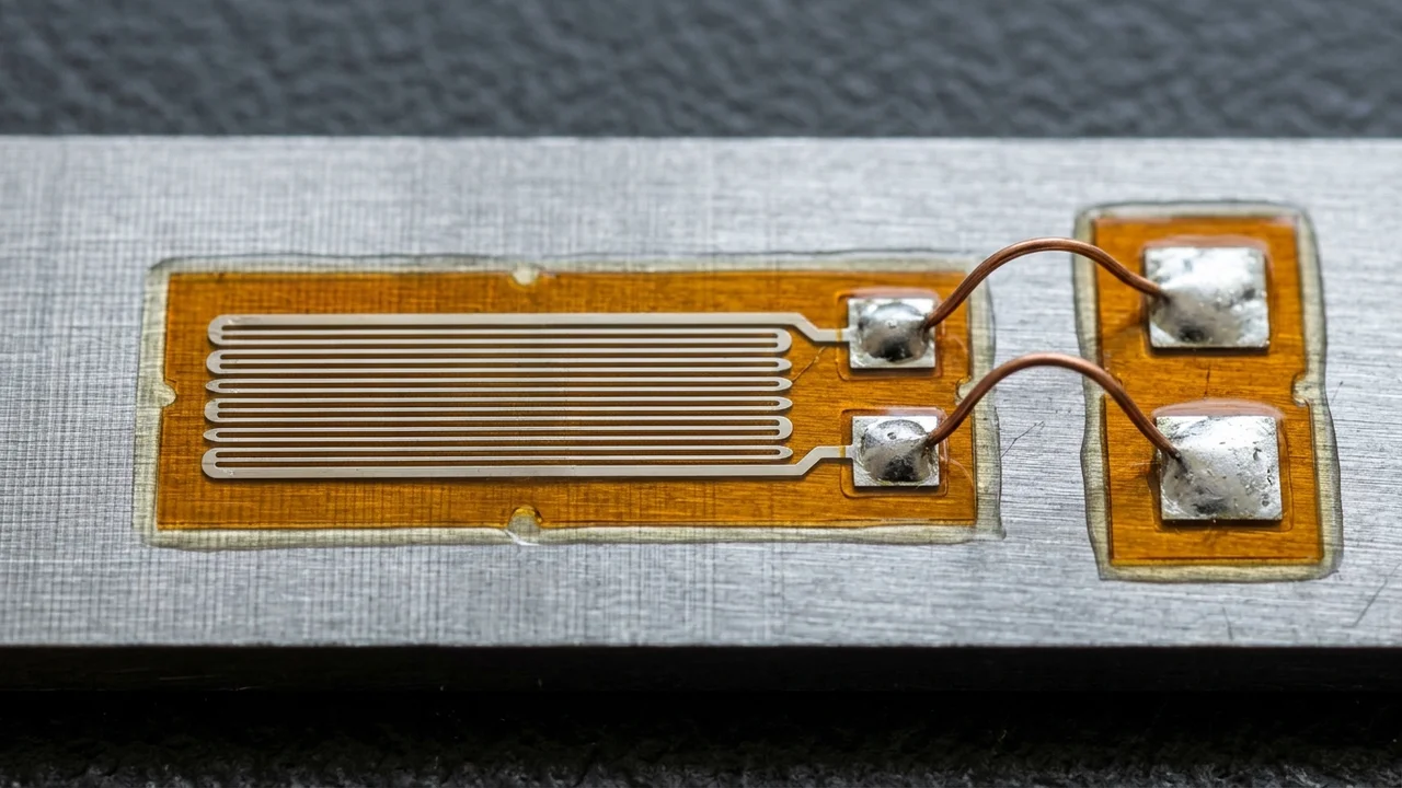
ASTM E251-20a describes methods and procedures for determining five metallic bonded resistance strain gage performance characteristics: resistance at a reference temperature (Part II), gage factor at a reference temperature (Part III), temperature coefficient of gage factor (Part IV), transverse sensitivity (Part V), and thermal output (Part VI). Under ASTM E251, most performance characteristics of strain gages require mechanical testing that is destructive; since test strain gages cannot be used again, it is necessary to treat data statistically and apply values to the remaining population from the same lot or batch, whereas resistance measurement is non-destructive and individual strain gages cannot be calibrated.
In general, a strain gage has two gage factors, Fa and Ft, which refer to the axial and transverse gage factors as determined in a uniaxial strain field, such that the unit resistance change in any strain field is ΔR/R = Fa εa + Ft εt = Fa (εa + Kt εt), where Kt = Ft / Fa is the transverse sensitivity coefficient. Transverse sensitivity in a strain gage refers to the behavior of the gage in responding to strains perpendicular to the primary sensing axis of the gage, and in the particular case of uniaxial stress in a material with a Poisson’s ratio of 0.285, the transverse-sensitivity error is zero because the manufacturer’s gage factor already includes the effect of the Poisson strain.
How Does Gauge Factor Enter Wheatstone Bridge and DAQ Strain Equations?
Because fractional resistance changes are small, strain gauges are wired into a Wheatstone bridge circuit. For a strain gage with a gage factor of 2.0, the output of a Wheatstone bridge circuit is (0.5 µV/V/µε) × N where N is the number of active arms: for a quarter-bridge (N = 1) with 10 VDC excitation the output is 5 µV per µε, whereas for a full-bending bridge (N = 4) with 10 VDC excitation the output is 20 µV per µε (or 0.5 × 10 × 1000 × 4 = 20,000 µV or 20 mV, which is 2 mV/V for 1000 µε); for a full Poisson axial bridge, N = 2 + (2 × ν).
In the generalized Wheatstone bridge equation with n active gages (n = 1 for a quarter bridge, n = 2 for a half bridge, and n = 4 for a full bridge) and reference output voltage Vo,reference, axial strain is εa ≈ (4 / n) [(Vo - Vo,reference) / Vs] (1 / S); for a quarter bridge (n = 1) with strain gage factor S = 2.0, supply voltage Vs = 5.00 V, and output Vo = 1.13 mV, the axial strain is 4 (1.13 mV / 5.00 V)(1 / 2.0)(1 V / 1000 mV) = 0.000452 = 452 µstrain (450 µstrain).
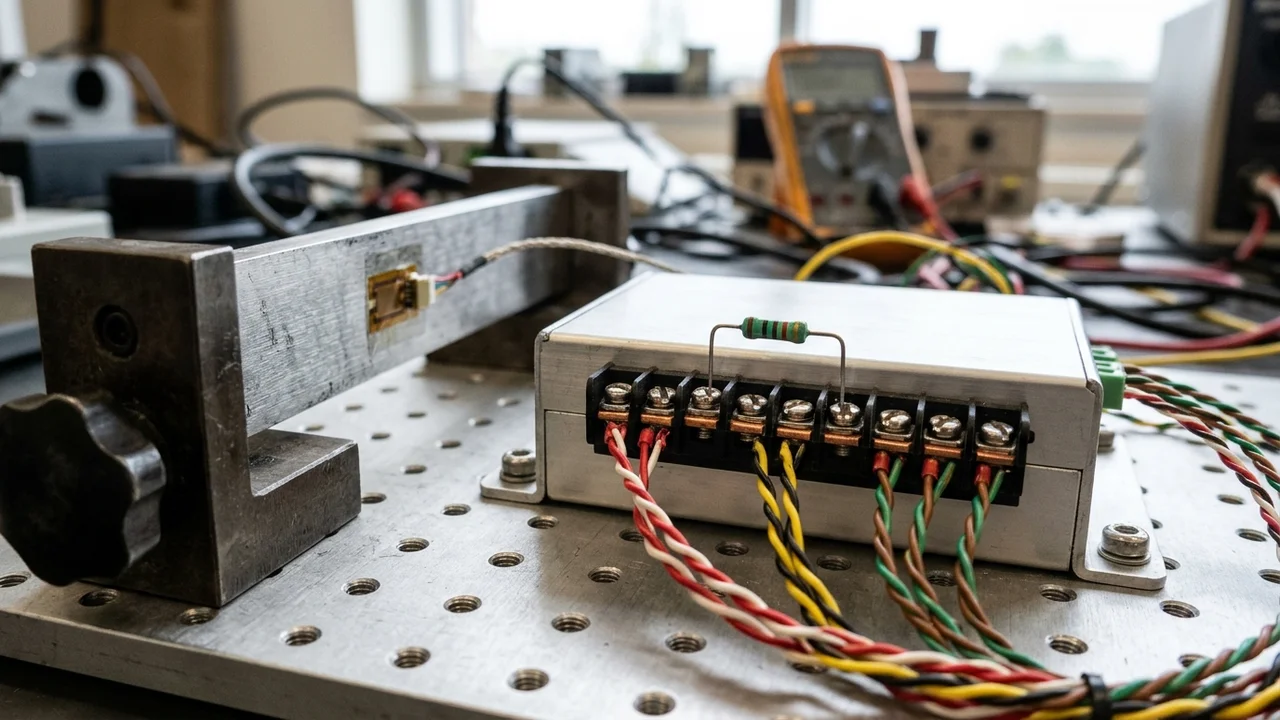
For a Quarter-Bridge Type I circuit (where sensitivity at 1000 με is ~0.5 mVout/VEX input), the voltage-to-strain conversion equation is strain (ε) = [-4 Vr / (GF (1 + 2 Vr))] × (1 + RL / Rg), where Vr = (VCH(strained) - VCH(unstrained)) / VEX, GF is the Gauge Factor, Rg is the nominal gauge resistance, and RL is the lead resistance. Higher resistance gages, like 350 Ω instead of 120 Ω, decrease the power per unit area dissipated, while when a 2-wire connection strain gage is 15 m long with a lead resistance RL equal to 1 Ω, the lead resistance adds 2 Ω to the arm of the bridge, which adds an offset error and reduces the sensitivity (and the temperature coefficient of copper lead wires is typically two orders of magnitude greater than the temperature coefficient of the gages). For practical lead-resistance checks and three-wire bridge connections, see our three-wire quarter-bridge checks guide.
Using bridge factor N across standard bridge configurations, Quarter-Bridge Type I and II (N = 1) use ε = -4Vr × (1 + Rl / Rg) / [GF × (1 + 2Vr)], Half-Bridge Type I (N = 1 + γ) uses ε = -4Vr × (1 + Rl / Rg) / [GF × (1 + γ) - 2Vr × (γ - 1)], Half-Bridge Type II (N = 2) uses ε = -2Vr × (1 + Rl / Rg) / GF = -4Vr × (1 + Rl / Rg) / (N × GF), Full-Bridge Type I (N = 4) uses ε = -Vr / GF = -4Vr / (N × GF), and Full-Bridge Type II (N = 2(1 + γ)) uses ε = -2Vr / [GF × (γ + 1)] = -4Vr / (N × GF). In a worked quarter-bridge calculation where a 120 Ω strain gage is wired with excitation Vex = 10V, sensor gauge factor GF = 2.0, lead resistance Rl = 0, and strained output Vo_strained = 3.500mV (Vo = 0.0035), the bridge sensitivity is Vr = Vo/Vex = 0.0035/10 = 0.00035 and the strain is ε = -4Vr × (1 + Rl / Rg) / [GF × (1 + 2Vr)] = -4 × 0.00035 / [2 × 1.0007] = -699.5 microstrain.
Shunt Calibration and Wheatstone Bridge Nonlinearity
The GF of common metallic strain gauges is typically ~2.0 and is used to compute simulated strain Es (micro-strain) = -Rg × 106 / (GF × N × (Rs + Rg)) (where shunt resistance is Rs = [Rg × 106 / (GF × N × Es)] - Rg at simulated strains ≤ 2000 micro-strain), whereas Instrument Gauge Factor is initially commonly set to 2.0 to calculate indicated strain. Shunt calibration is a process used to obtain a gain adjust factor = (simulated signal level) / (measured signal level with shunt resistor engaged), which corrects for system gain error and discrepancies between nominal Gauge Factor and actual Gauge Factor; offset null compensation must be performed just before performing a shunt calibration.
Load cells are much simpler than strain gauge bridges because their relationship to load does not require additional detail of how internal bridge elements are arranged, Gauge Factor, or the Poisson’s ratio of the material it is applied to; the only important considerations for resolving the load cell are its rated output (mV/V), excitation voltage, and rated capacity. When deciding between bonding discrete foil gauges and installing a calibrated force transducer, see our strain gauge versus load cell comparison.
For TN-507 Cases 1, 2, 4, and 5 (intrinsically nonlinear bridge/strain arrangements), the nonlinearity error is about 0.1% at 1000 µε, 1% at 10 000 µε, and 10% at 100 000 µε (as a convenient rule of thumb, the error in percent is approximately equal to the strain in percent), while the output expressions for Cases 3, 6, and 7 are linear. For a single active gage in a quarter-bridge with F = 2.0 where a strain indicator registered εi = 15 000 µε in tension (approximately 1.5 percent or about 225 µε error), substituting into the expression ε = (2 εi)/(2 - F εi × 10 –6) gives ε = 15 228 µε, and if the strain indicator had read –15 000 µε for compression it gives –14 778 µε, because bridge nonlinearity causes indicated tensile strains to be too low and indicated compressive strains too high.
How Do You Rescale Indicated Strain for Instrument Gauge Factor and Temperature?
The gage factor of the strain gage (FG) is distinguished from the gage factor setting of the measuring instrument (FI), and thermal output in strain units registered by an indicator set at FI is εT/O = [βG + FG ((1 + Kt)/(1 - ν0 Kt))(αS - αG)] ΔT / FI, where ν0 = 0.285 is Poisson’s ratio. The correction factor for transverse sensitivity [(1 + Kt)/(1 - ν0 Kt)] is included in that thermal output equation to account for the fact that the strain in the gage grid due to differential thermal expansion is equal-biaxial, while the gage factor FG refers to the strain sensitivity as calibrated in a uniaxial stress state with a principal strain ratio of 1/(–0.285).
For each lot of A-alloy and K-alloy gages, Micro-Measurements supplies a regression-fitted (least-squares) polynomial equation εT/O = A0 + A1 T + A2 T^2 + A3 T^3 + A4 T^4 based on an instrument gage factor of 2.0; if the instrument is set to an instrument gage factor FI other than 2.0, the Ai coefficients in that polynomial can be multiplied by the ratio 2.0/FI.
Gage factor variation with temperature in the A alloy (constantan) is essentially linear and quite small at any temperature, typically being in the order of 1% or less per 100°F [2% or less per 100°C], whereas for modified Karma (K alloy) the slope is negative and is a function of the S-T-C number, becoming steeper with higher numbers. Any strain ε1 registered with the strain indicator gage factor set at F1 is corrected to an actual or test-temperature gage factor F2 = F1 (1 + ΔF(%)/100) using ε2 = ε1 × (F1 / F2); for a 13 S-T-C, K-alloy gage with room-temperature gage factor F1 = 2.05 at +450°F [+230°C] where ΔF(%) is –3, F2 = 2.05 (1 – 0.03) = 1.99, and an indicated strain of 1820 µε corrects to ε2 = 1820 × (2.05 / 1.99) = 1875 µε.
The instrument gage factor setting should not be changed during a test (after zero-balance), since this may introduce a zero shift; when the indicator is balanced at room temperature with instrument gage factor FI = 2.0, combining the thermal output and test-temperature gage factor corrections yields ε1 = [ε̂1 - εT/O(Ti)] × [2.0 / F(Ti)].
When Must You Correct for Transverse Sensitivity (Kt)?
In plane wire strain gages, transmission of strain into the wire from a direction perpendicular to the wire axis is nearly negligible so the sign of the transverse sensitivity for a plane wire gage will always be positive, whereas in foil strain gages the foil gridlines having a large ratio of width to thickness are strained significantly and the transverse sensitivity can be either positive or negative.
Any strain gage which is (a) installed on a material with a different Poisson’s ratio, (b) installed on steel, but subjected to other than a uniaxial stress state, or (c) installed on steel with a uniaxial stress state, but aligned with other than the maximum principal stress, exhibits a transverse-sensitivity error which may require correction. For substitution into any transverse-sensitivity correction equation, Kt must always be expressed decimally, so the value of Kt (in percent) from the gage package data sheet must be divided by 100 for conversion to its decimal equivalent.
The percentage error nε in indicated strain due to transverse sensitivity in any strain field is nε = [Kt (εt/εa + ν0) / (1 - ν0 Kt)] × 100, and as long as the absolute value εt/εa is not close to ν0, an approximate rule-of-thumb for quickly estimating the error due to transverse sensitivity is nε ≈ Kt (εt/εa) × 100 (percent). If the test specimen is an aluminum alloy with ν = 0.32, then when measuring transverse Poisson strain in uniaxial stress εt/εa = –1/ν = –3.1; assuming that the transverse sensitivity of the strain gage is –3% (i.e., Kt = –0.03), the rule of thumb gives an approximate error of +9.3%, while the actual error calculated from the exact equation is +8.5%.
How Do You Correct Two-Grid and Three-Grid Rosette Readings for Kt?
For the general biaxial stress state with principal directions unknown, three independent strain measurements (in different directions) are required to determine the principal strains and stresses. All gages in a stacked rosette have the same gage factor and transverse sensitivity, while the grids in a planar rosette will differ slightly in these properties due to their different orientations relative to the rolling direction of the strain-sensitive foil, and the technical data sheet accompanying the rosettes fully documents the separate properties. Because at least one of the gage grids in any rosette will in every case be subjected to a transverse strain which is equal to or greater than the strain along the grid axis, consideration should always be given to the transverse-sensitivity error in rosette data reduction; in general, when Kt ≤ 1%, the transverse-sensitivity error is small enough to be ignored, whereas at larger values of Kt correction for transverse sensitivity may be necessary.
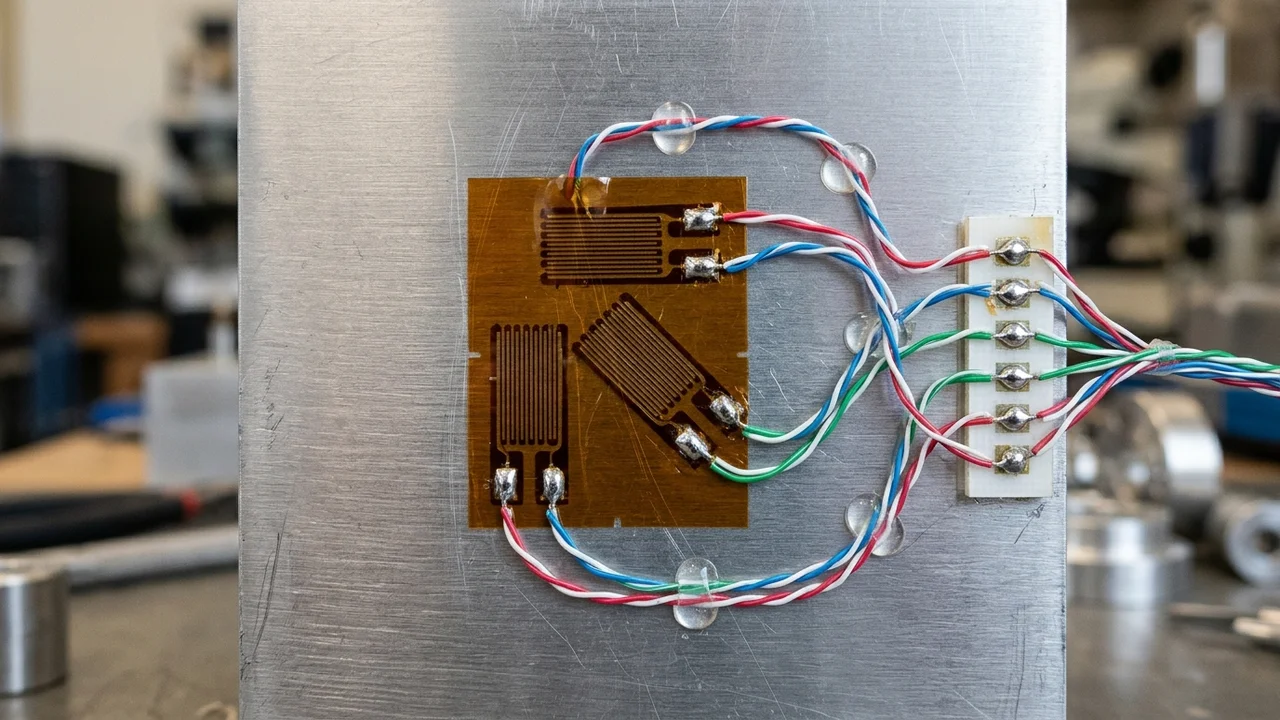
For a two-gage 90-degree rosette with the gage axes aligned with two orthogonal axes, x and y, on the test surface, the corrected strains are εx = (1 - ν0 Kt)(ε̂x - Kt ε̂y)/(1 - Kt^2) and εy = (1 - ν0 Kt)(ε̂y - Kt ε̂x)/(1 - Kt^2), where the (1 - Kt^2) term in the denominators is generally in excess of 0.995 and can be taken as unity: εx = (1 - ν0 Kt)(ε̂x - Kt ε̂y) and εy = (1 - ν0 Kt)(ε̂y - Kt ε̂x). For a two-gage, 90-degree rosette with elements (1) and (2) indicating ε̂1 = +1530 µε and ε̂2 = +920 µε, assuming Kt = –0.06 and ν0 = 0.285, the corrected strains are εx = (1 + 0.285 × 0.06)(1530 + 0.06 × 920) = 1612 µε and εy = (1 + 0.285 × 0.06)(920 + 0.06 × 1530) = 1029 µε.
When the two gage elements of a two-gage, 90-degree rosette (or T-rosette) are connected in adjacent arms of a Wheatstone bridge for the direct indication of shear strain along the bisector, the transverse-sensitivity correction factor is Cγ = (1 - ν0 Kt)/(1 - Kt), or the gage factor control can be set to Fγ = F (1 - Kt)/(1 - ν0 Kt).
In a three-gage rectangular (45°) rosette with equal transverse sensitivity Kt, the orthogonal outer elements (1) and (3) and center grid (2) are corrected as ε1 = [(1 - ν0 Kt)/(1 - Kt^2)] × (ε̂1 - Kt ε̂3), ε2 = [(1 - ν0 Kt)/(1 - Kt^2)] × [ε̂2 - Kt(ε̂1 + ε̂3 - ε̂2)], and ε3 = [(1 - ν0 Kt)/(1 - Kt^2)] × [ε̂3 - Kt ε̂1]. With any rosette, rectangular, delta, or otherwise, it is always possible to calculate the indicated principal strains directly from the completely uncorrected gage readings and then apply corrections to the principal strains via εp = [(1 - ν0 Kt)/(1 - Kt^2)] × (ε̂p - Kt ε̂q) and εq = [(1 - ν0 Kt)/(1 - Kt^2)] × (ε̂q - Kt ε̂p). The indicated strains from three gages with any relative angular orientation define an indicated Mohr’s circle of strain; to correct the indicated Mohr’s circle to the actual Mohr’s circle, the distance to the center of the indicated circle should be multiplied by (1 – ν0 Kt)/(1 + Kt), and the radius of the circle by (1 – ν0 Kt)/(1 - Kt).
Pre-Test Verification Sequence for Strain Gauge Sensitivity Scaling
Before converting raw bridge voltages or indicator readings into engineering strain, record and verify these channel parameters from your strain gauge package data sheet and signal conditioner setup:
- Record the statistical lot or batch gauge factor values for the remaining population from the same lot or batch, since individual strain gauges cannot be calibrated.
- Divide the printed percentage transverse sensitivity by 100 to obtain its decimal equivalent before substituting into any biaxial or rosette correction equation.
- Verify whether the grid is a single element, a stacked rosette with uniform properties across grids, or a planar rosette with separate grid properties documented on the package sheet.
- Keep the instrument gauge factor setting fixed after zero-balance during elevated-temperature tests and apply thermal output and test-temperature gauge factor rescaling in post-processing.
- Perform offset null compensation immediately before engaging the shunt calibration resistor when verifying bridge amplifier gain.
Sources
- ASTM International — ASTM E251-20a Standard Test Methods for Performance Characteristics of Metallic Bonded Resistance Strain Gages
- Vishay Micro-Measurements — Tech Note TN-509 (Document Number 11059): Errors Due to Transverse Sensitivity in Strain Gages
- Vishay Micro-Measurements — Tech Note TN-504-1: Strain Gage Thermal Output and Gage Factor Variation with Temperature
- Vishay Micro-Measurements — Tech Note TN-507-1: Errors Due to Wheatstone Bridge Nonlinearity
- Vishay Micro-Measurements — Tech Note TN-515: Strain Gage Rosettes: Selection, Application and Data Reduction
- Vishay Micro-Measurements — Use of the Full Wheatstone Bridge in Experimental Stress Analysis
- National Instruments — SCXI-1520 User Manual
- National Instruments — Engineer’s Guide to Accurate Sensor Measurements
- Acromag — Whitepaper 8500-699: Introduction to Strain & Strain Measurement
- Penn State University Department of Mechanical Engineering — Stress, Strain, and Strain Gages (John M. Cimbala)
- Penn State University Department of Mechanical Engineering — ME 345 Lab 8: Strain Gage Lab (John M. Cimbala)
- Keyence — What is Strain, Types, & How to Calculate
- Vibration Research — Introduction to Strain Gauges for Stress Analysis